Most thermal sensor cable orders go wrong long before the cable ships — they go wrong on the spec sheet. A field is missing, a tolerance is undefined, or a paragraph mixes activation temperature with ambient temperature. Three months later the buyer is in a meeting trying to explain why "the same cable" reads 12 K higher than what was promised, and the conversation is no longer technical, it is contractual.
This page is a thermal sensor cable specification guide written from the spec sheet outward. It is not a selection framework — for the LHD-versus-TS and overall decision tree, see our five-step selection framework for thermal sensor cable. This page assumes you have already decided which family of cable you are buying. It walks twelve fields a thermal sensor cable specification sheet should contain, the engineering trade-off behind each, and the wording that survives a three-party review. After this page, you should be able to hand the spec sheet to procurement, your QA lead and a field engineer, and have all three sign without rewriting the cable section.
The structure is intentional. Each field is its own section, with three things — what the field is, the engineering trade-off behind it, and the line of contract wording it produces. A real thermal cable spec writing checklist is twelve such triples. If you have ever asked an engineering desk how to specify thermal sensor cable for a real project, this is the answer in long form: skip a field and the order will eventually surface the gap; combine two fields and the order will surface the failure mode of whichever one you compressed.
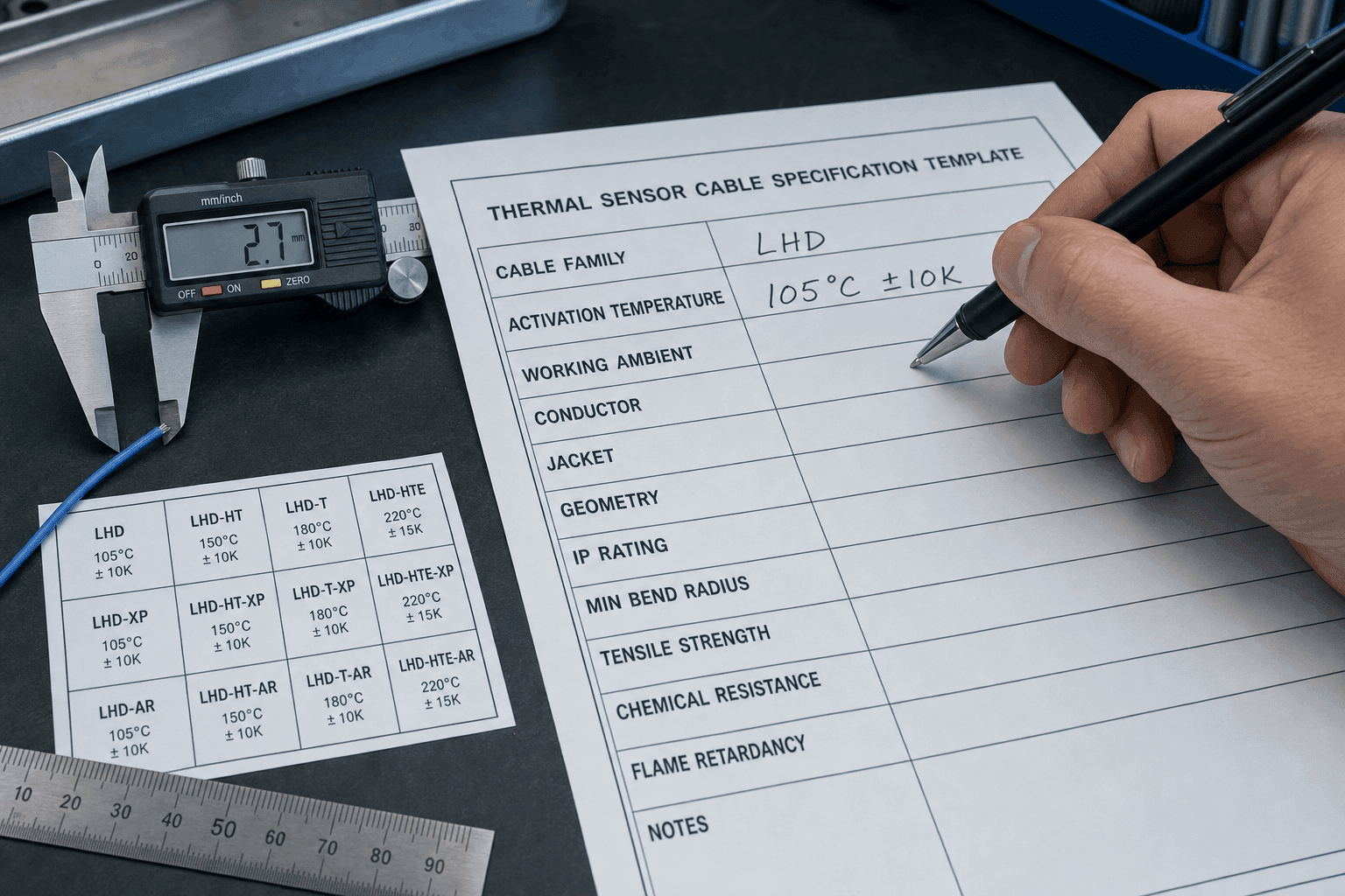
Field 1 — Cable Family (LHD or TS)
Every thermal sensor cable specification sheet opens with one declaration: this is a Linear Heat Detection (LHD) cable, or this is a Thermosensitive (TS) cable. The two families have different jackets, different colours, different terminations, different test methods and different compliance scopes. Letting "thermal cable" stand on the field-one row forces the supplier to guess which one you want — and a guess priced into a quote will be re-priced when the deployment shows up.
How to phrase the family decision in one sentence
Either "Linear heat detection cable for the route described in §x" or "Thermosensitive cable for in-device over-temperature cut-off in the host described in §x." Anything more complicated is wrong; anything less specific is also wrong.
The single most common mistake
Leaving the field as "thermal cable" or "fire detection cable" without the family abbreviation. The spec sheet has eleven fields downstream of this one — every single downstream field is family-conditional. A sheet that does not commit Field 1 cannot be reviewed.
If the project is still in the family-decision phase, do not write a spec sheet — go back to the five-step selection framework linked at the top of this page and resolve LHD-versus-TS first. Spec writing starts after that decision, not before. And if the project has not yet settled on a thermal sensor cable versus a point thermistor or thermocouple at all, that sensor-type decision sits one level above the family choice — it is covered in thermal sensor cable vs NTC thermistor vs thermocouple.
Field 2 — Activation Temperature
Field 2 is the number most spec sheets open with: the activation temperature. The spec sheet must commit to one of two paths — a standard six setpoint, or a documented custom point — and must commit to a tolerance band on top of either path.
Standard six (68 / 88 / 105 / 138 / 170 / 185 °C) or custom setpoint
The standard six are not arbitrary. They map to common ambient envelopes — 68 °C for cold-storage and refrigerated rooms, 88 °C for office and data-center ceilings, 105 °C for indoor industrial, 138 °C for warehouses with summer ambients, 170 °C for tunnels and process plants, 185 °C for turbine halls and high-bay refineries. Specifying a standard point is faster, cheaper and easier to second-source. Specifying a custom point — common for EV battery packs at 95 °C, or for motor windings at 130 °C matched to insulation Class B — adds engineering review time and typically narrows your supplier list.
Tolerance band — ±5, ±10 or ±15 K and what each costs
Tolerance is the line item most spec sheets forget. A 170 °C cable at ±15 K alarms anywhere between 155 and 185 °C, which is fine on an open ceiling and wrong on a server room rated for 35 °C ambient with a 30 °C nuisance margin. A tighter tolerance — ±10 K, ±5 K — materially increases the QC effort on the production line and demands tighter compound formulation control. Pick the tolerance the deployment needs, not the tolerance the supplier prefers — and document the choice in writing. Our companion guide on activation-temperature setpoint selection against the standard six goes deeper on the cost curve.
When the tolerance band can stay loose
A tighter tolerance is not free, and on routes where the activation point already sits well above any plausible working ambient — open-ceiling spaces, atmospheric warehouses, outdoor cable trays under shade — a ±15 K band already buys all the headroom the deployment needs. Tightening from ±15 K to ±5 K on a sheet that already has 25 K of headroom does not make the system safer; it narrows the supplier list and inflates QC cost without changing the alarm point a buyer will ever see. The standard six setpoint at the loosest tolerance the headroom rule allows is usually the right answer; tighter is something the deployment has to ask for, not something the spec sheet tightens by default.
Field 3 — Working Ambient Temperature (Must Not Share a Row With Field 2)
Field 3 is the field every loose spec sheet collapses into Field 2 — and every collapsed sheet eventually fails review. The activation temperature is the point at which the cable triggers; the working ambient temperature is the temperature the cable lives at, every day, for years of service, without alarming. They are different physical quantities. They live on different rows.
Why "120 °C cable" without a working-ambient line is meaningless
Take a sheet that reads "120 °C thermal cable, 50 m." The supplier reads it as either "activate at 120 °C" or "rated for 120 °C ambient" — and ships whichever interpretation is cheaper. Two reasonable engineers in the buyer's office and the supplier's office can read the same row and reach opposite conclusions. The fix is not a longer sentence; it is two rows.
The 20–30 K headroom rule
For most LHD applications, set the activation point 20 to 30 K above the highest sustained working ambient the cable will see — including seasonal peaks and adjacent equipment thermal drift. A 80 °C ambient with a 105 °C activation gives 25 K of headroom and tolerates a ±15 K tolerance band; the same 80 °C ambient with an 88 °C activation point sits inside the tolerance window and will nuisance-alarm. The headroom rule is geometry, not opinion. Spell it out on the spec sheet so procurement does not negotiate it away on cost grounds. Establishing that highest-sustained ambient figure in the first place — what it includes and how to survey a route for it rather than quote a nameplate — is the subject of the working ambient versus activation temperature note.
Field 4 — Conductor Alloy
For the bulk of LHD and TS deployments the conductor is a copper-based pair — tinned-copper or nickel-plated copper — and Field 4 is satisfied with one row. Field 4 starts to separate a real specification from a brochure when the cable runs at sustained-high ambient (above ~150 °C), when the conductor itself is expected to carry meaningful heat, or when the design uses a resistance-wire-based sensing topology. In that band, NiCr, FeCrAl and the nickel-superalloy family each have different resistivity, different temperature-coefficient linearity and different long-term drift behaviour. The spec sheet should name the alloy class and, for high-stakes applications, the specific grade.
NiCr vs FeCrAl vs superalloy in one paragraph each
Within the high-temperature / resistance-wire band, NiCr (Ni80Cr20) is the engineering default — linear TCR across the activation range, predictable oxide layer, well-behaved at terminations. FeCrAl (Kanthal A1) is cheaper at the conductor-meter level, runs hotter for the same resistance, and degrades faster in chloride and sulfide atmospheres. Nickel superalloy is reserved for sustained-high-temperature applications above 200 °C ambient where NiCr drift exceeds the tolerance band. The detailed comparison sits in our Ni80Cr20 versus Kanthal A1 conductor decision; the framework spanning all three sits in the conductor alloy framework for NiCr, FeCrAl and superalloy. None of this applies to a standard ambient-rated LHD or TS run on copper — there, the row is "tinned-copper or nickel-plated copper" and the discussion ends.
The contract wording that locks the alloy
"Conductor: Ni80Cr20, certificate of conformity per shipped lot, batch traceability to the raw-material heat number." That sentence is enforceable. "High-quality alloy" is not.
Field 5 — Jacket Material
Field 5 is where the spec sheet meets the deployment environment. The jacket is the polymer between the working ambient and the thermosensitive compound; it dominates chemical resistance, mechanical durability, smoke-toxicity behaviour and a meaningful share of the cable's unit cost.
PVC, LSZH, silicone, fluoropolymer or fiberglass
PVC handles indoor low-cost runs to roughly 70 °C ambient and fails most tunnel codes on smoke toxicity. LSZH (low-smoke zero-halogen) is the default for tunnels, metros, public buildings and any application where local fire codes require low-smoke and halogen-free jackets — IEC 60754 covers halogen content, IEC 61034 covers smoke density, IEC 60332 covers flame propagation. Silicone tolerates 180 °C ambient and is the practical choice next to high-wattage motors and transformers. PTFE, PFA and FEP fluoropolymers handle chemical environments, oil mist and ambients up to about 260 °C continuously for PTFE / PFA and about 200 °C continuously for FEP, at three to five times the unit price of LSZH. Fiberglass-braided jackets reach 600 °C ambient for industrial-heater-adjacent runs but lose mechanical robustness in routes that need flex life. The dedicated silicone vs PTFE vs fiberglass insulation comparison walks the property tables side by side; the companion jacket material decision matrix turns those properties into a five-axis selection tool you can paste straight into the spec sheet.
The contract wording that locks the jacket
Name the polymer family, the working ambient ceiling, and the relevant code references in one row — for example, "Jacket: LSZH compound, working ambient — 90 °C, halogen-free per IEC 60754, smoke density per IEC 61034."
When the jacket should stay simple
Jacket choices stack cost quickly, and over-spec'ing this row is one of the more expensive habits on a thermal cable RFQ. PTFE is the right answer next to oil mist, chemical attack or sustained ambients above 200 °C — it is rarely the right answer for a dry indoor switchroom, where LSZH or even PVC handles the same route at a fraction of the unit price. LSZH itself is not a default for every project; on a private industrial site with no halogen-free code obligation, the LSZH premium buys nothing the deployment will ever measure. Fiberglass tolerates 600 °C ambient but loses bend life in routes that need flex — putting it on a frequently re-routed cable tray trades one failure mode for another. Match the jacket to the working ambient ceiling, the chemistry, the code obligation and the mechanical duty, in that order; anything beyond what those four ask for is jacket the project paid for and never needed.
Field 6 — Geometry & Cross Section
Field 6 carries two decisions in one row: the outer diameter, and the internal architecture of the cable.
Diameter ranges by family
LHD cable runs at 2.5 to 3.0 mm outer diameter — sized for cable-tray installation hardware, EOL resistor terminations and the spool sizes the integration trade expects. TS cable runs at 1.5 to 2.0 mm outer diameter — sized to fit motor slot liners, battery aisle gaps and PCB cable channels. Specifying a 3.0 mm diameter for a TS application or a 1.8 mm diameter for an LHD application is technically possible but practically problematic; the field engineering trades will resist a non-standard diameter even if the cable is correct.
Metal-core vs non-metal-core architecture
Below the jacket, two architectures dominate. The metal-core architecture pairs two metallic conductors — typically tinned-copper or nickel-plated copper for ambient-rated LHD/TS, or a NiCr resistance pair for high-temperature variants — separated by a thermosensitive compound — the conductors trigger a short across the compound at activation temperature. The non-metal-core architecture relies on the thermosensitive compound itself as the resistive path, with no continuous metallic conductor through the active section. The metal-core variant gives a faster, sharper activation and accepts standard EOL termination hardware; the non-metal-core variant is mechanically more robust, simpler to terminate and typically lower in unit cost. The dedicated cross-section comparison of metal-core and non-metal-core architectures sits in a separate engineering note — five engineering axes, five deployment-scenario reverse-lookups and three substitution detection signals — and the architecture choice should be written into Field 6 explicitly so the supplier cannot substitute one for the other on cost grounds.
When the architecture choice is decisive — and when it is not
The metal-core vs non-metal-core decision earns its row when the route punishes the cable mechanically — heavy vibration, foot traffic, conveyor crush, sharp bend reversals — or when the install crew needs the simplest possible termination on site. On clean cable-tray runs with standard EOL hardware and a panel the integrator has wired before, panel-side maintenance teams generally do not see a difference between the two architectures, and the choice quietly defaults to whichever variant the integrator has parts for. Spell it out anyway, but treat it as a downstream-driven decision: settle Field 5 (jacket) and Field 8 (mechanical envelope) first, then let the architecture follow what those two require.
Field 7 — Ingress Protection (IP Rating)
The IP rating is two digits and is non-negotiable for any thermal sensor cable that will see water, dust or condensation. IP67 covers short-duration immersion to roughly one metre for thirty minutes and handles wash-down, condensate runs and rainy-season cable-tray exposure. IP68 covers continuous immersion to a manufacturer-declared depth and duration, beyond the IP67 condition, and is the right choice for tunnel drainage routes, underground substations and any deployment where water can stand around the cable for hours.
The mistake to avoid is implying an IP rating through jacket choice — silicone is not automatically IP68, LSZH is not automatically IP67. The IP rating comes from the cable's overall construction, including the inner sheath and the termination procedure, and must be tested and stated explicitly. A spec sheet without an IP row tells the supplier you do not know what the deployment looks like.
When IP68 quietly creates risk
IP68 is not a free upgrade over IP67. On a dry, sheltered route that is not washed down and has no condensation cycle, IP67 — or even an unrated jacket on a properly routed tray — covers the deployment at noticeably lower cost. Writing IP68 into the spec when the on-site termination procedure can only deliver IP66 creates a verification gap: the cable section passes its bench test, the as-installed system fails commissioning, and the supplier has the contractual point that the cable itself meets the row. Match the IP rating to the wettest hour the route will see — wash-down, condensate, seasonal flooding — and check the termination kit and installation procedure against the same number before signing.
Field 8 — Mechanical Envelope
Field 8 covers what the cable has to survive physically — bend radius, tensile strength and crush resistance. Each is a separate number; collapsing them into "rugged construction" is the kind of phrase that reads well in a brochure and badly in an arbitration letter.
Bend radius, tensile, crush rating
Specify a minimum bend radius of six times the outer diameter as a baseline; tighter bends require a documented heat-treatment or a flexible-grade compound. Specify a tensile strength threshold — typical LHD cable holds 200 N over a 50 mm gauge length without compound delamination. Specify a crush rating in N per millimetre of cable length, sized to the heaviest mechanical event the route will see — installer foot traffic, conveyor support hardware, vibration clamps. Each number lives on its own row, with a referenced test method. For the full treatment of these three figures — static versus dynamic bend radius, what an over-tight bend does to the core, and how the envelope reaches the drawing — see the bend radius and mechanical envelope note.
Field 9 — Termination Strategy
Termination is the field every spec sheet under-specifies because the trade-off is invisible until the cable is on the panel.
Field 9 also carries a materials dimension the resistor value alone does not capture: the metallurgy of the joint itself. The conductor end — tinned or nickel-plated copper on an ambient-rated cable, a high-temperature alloy on a resistance-wire build — lands on a brass, tinned-copper or stainless terminal, and a poorly matched pairing left damp slowly corrodes into rising contact resistance over years of service. On a damp, warm or hard-to-inspect route it is worth naming the conductor end metallurgy and plating, and a sealed termination, alongside the EOL value; the mechanism and the specification detail sit in the termination metallurgy, aging and drift note.
End-of-line resistor for LHD
For LHD installations the spec sheet must call out the end-of-line resistor value — typically 4.7 kΩ or 10 kΩ depending on the panel — and the supervision current the panel expects on a healthy loop. The cable does not pick this number; the panel does. The spec writes the panel's number into the cable agreement so a future panel swap can be costed without re-sourcing the cable, and the EOL value sits on its own row of the spec sheet next to the panel make and model.
Appliance cut-off path for TS
For TS installations the spec sheet describes the cut-off path — which conductor opens, what the host product expects on activation, whether the cable is one-shot fusible or resettable PTC. The host integration drives this; the spec records the host's answer. Pick one of the two cut-off behaviours, write it into Field 9 in plain language, and keep the corresponding host design note in the project file alongside the spec sheet.
When termination is not the row to negotiate
Termination strategy is panel-driven on LHD and host-driven on TS — neither decision is the cable supplier's to make, and neither is the spec sheet's to invent. If the panel make and model are already on the project drawing, the EOL value and supervision current are inputs to Field 9, not negotiables; the row exists to record the panel's number so a future panel swap is costed correctly. The same is true for TS: if the host product is in production, the cut-off path was decided before the cable RFQ existed. Field 9 carries the most contractual weight when those upstream decisions are still open and the spec is being drafted in parallel with panel selection or host design — and the least, when the project file already has both numbers.
Field 10 — Compliance Documents (the Document Package)
Field 10 is the row procurement actually reads. It names the document package the supplier ships with the cable — not the package the supplier mentions in marketing.
The baseline four
ISO 9001 QMS certificate, RoHS or REACH declaration, regional CE or UL compliance evidence appropriate to the destination market, and a per-batch test report keyed to the lot number printed on the cable jacket. These four are the minimum a spec sheet should require. A supplier that cannot produce the three standing documents at the RFQ stage — and commit to a per-batch test report keyed to the lot with every shipment — is not a supplier you finish the evaluation with.
The conditional five
LSZH halogen-free certification (tunnels, metros), IEC 60332 flame-propagation data (public-building runs), UL VW-1 vertical-wire flame test (consumer and EV applications), local fire-code AHJ approval (fire-protection projects), and the European line-type LHD type-test report keyed to product class — EN 54-22 for resettable line-type heat detectors, EN 54-28 for non-resettable (fusible) line-type heat detectors. Add these as required by the deployment. How a buyer should read each of these standards — and why a claim of designed against is not the same as a certificate from a recognised body — is the compliance map for EN 54-22, UL 521 and FM 3210.
The buyer-side counterpart to this list — how to evaluate whether a supplier can actually produce these documents on demand, what red flags to read in the answers, and how the document package fits into a four-stage supplier evaluation flow — is the subject of our thermal sensor cable supplier evaluation guide, a four-stage decision path from desk research through document review to incoming inspection. The request list itself — which documents to ask for, what each one proves and when in the buying process to ask — is set out in the document package every buyer should request.
Field 11 — Per-Batch QC Requirements
Field 11 turns the spec sheet from a one-time document into an ongoing contract. The buyer requires the supplier to attach an inspection report to each shipped lot — and the spec sheet defines what that report must contain.
What to require in the spec, what to verify on the report
Require the supplier to attach a per-batch inspection report to every shipment. The report carries a reportable-parameter layer (appearance, outer diameter, conductor resistance, insulation resistance at 500 V, activation temperature, dielectric withstand voltage, length per reel, jacket marking and packing); the values on that report come out of a separate test-method layer with its own pass thresholds. Our nine-parameter QC checklist walks the test-method layer; our thermal sensor cable supplier evaluation guide walks a buyer-side reading of the report itself. Field 11 specifies that both layers are required — the spec sheet can reference the two pages above rather than re-name them inline.
The contract wording that locks per-batch QC
"Each shipped lot is accompanied by an inspection report listing the nine QC parameters defined in §x, signed by the supplier's QA lead, with measured values keyed to the lot number printed on the cable jacket." That sentence is auditable; "quality controlled" is not.
Field 12 — RFQ-Ready Wording
Field 12 is the row that turns a spec sheet into a Request for Quote. It names the trailing fields a procurement system needs in order to issue a PO — delivery schedule, packaging convention, marking convention, document delivery format and acceptance criteria.
How to attach this spec to an RFQ template
The cleanest pattern is a one-page cover that names the project, references the eleven preceding fields by number, and adds five RFQ-specific lines: required quantity in metres or spools, target ship date, packaging (50 m reels, 500 m drums, custom OEM packaging), per-cable marking requirement (lot number, activation temperature, batch date) and document delivery channel. The thermal sensor cable RFQ template walks the twelve-field RFQ structure that pairs with this guide — three of its fields point back into this spec sheet (architecture, activation tolerance, geometry), and the other nine cover the project-context, compliance and commercial layers a spec sheet does not carry. Once the RFQ goes out and sample reels come back, the cross-check that those reels actually match the twelve fields written here is in the sample evaluation procedure note.
The Twelve Fields at a Glance
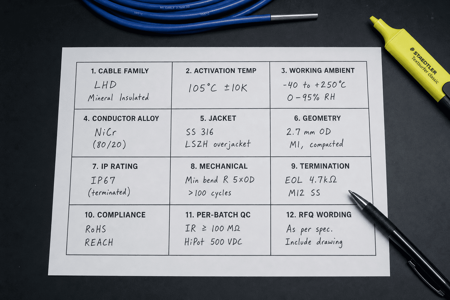
Treat the table below as a thermal cable specification template — twelve rows, twelve trade-offs, ready to drop straight into your project's spec document or RFQ cover sheet.
| # | Field | Engineering trade-off |
|---|---|---|
| 1 | Cable Family | LHD vs TS — every downstream field is family-conditional |
| 2 | Activation Temperature | Standard six setpoint vs custom; tolerance band ±5 to ±15 K |
| 3 | Working Ambient | Separate row from Field 2; 20–30 K headroom rule |
| 4 | Conductor Alloy | NiCr default; FeCrAl cheaper but atmosphere-sensitive; superalloy for > 200 °C ambient |
| 5 | Jacket Material | PVC / LSZH / silicone / fluoropolymer / fiberglass; dominates unit cost |
| 6 | Geometry & Cross Section | Diameter by family; metal-core vs non-metal-core architecture |
| 7 | IP Rating | IP67 short immersion; IP68 continuous to a declared depth; never implied through jacket |
| 8 | Mechanical Envelope | Bend radius, tensile, crush — three numbers, three rows |
| 9 | Termination Strategy | EOL resistor for LHD; cut-off path for TS |
| 10 | Compliance Documents | Baseline four + conditional five |
| 11 | Per-Batch QC | Nine-parameter inspection report keyed to lot number |
| 12 | RFQ Wording | Five-line cover that turns the spec into a PO request |
A thermal sensor cable specification sheet is twelve fields, twelve engineering trade-offs, and twelve lines of contract wording. Anything shorter is a brochure; anything longer is paperwork. The discipline is to write each field once, in the right wording, and let the spec defend the project for ten years.
FAQ — Thermal Sensor Cable Specification Guide
What twelve fields belong in a thermal sensor cable specification sheet?
A complete thermal sensor cable spec sheet contains twelve named fields: (1) Cable Family — LHD or TS; (2) Activation Temperature — standard six setpoint or custom; (3) Working Ambient Temperature — separate line, never combined with Field 2; (4) Conductor — tinned-copper or nickel-plated copper for ambient-rated deployments, NiCr / FeCrAl / superalloy for sustained-high-temperature variants; (5) Jacket Material — PVC, LSZH, silicone, fluoropolymer or fiberglass; (6) Geometry & Cross Section — diameter and metal-core or non-metal-core architecture; (7) Ingress Protection — IP rating; (8) Mechanical Envelope — bend radius, tensile, crush; (9) Termination Strategy — EOL resistor or appliance cut-off path; (10) Compliance Documents — the document package; (11) Per-Batch QC Requirements — what the buyer requires on the inspection report; (12) RFQ-Ready Wording — how the spec attaches to the purchase request. Each field carries an engineering trade-off and a piece of contract leverage; a sheet missing any one of them is a sheet a procurement team cannot defend.
How is a specification sheet different from a selection framework?
A selection framework answers What — should this project use LHD or TS, roughly which activation temperature, what kind of jacket, what compliance scope. Our five-step selection framework handles that layer. A specification sheet answers How — given those decisions, which exact field values go on the document procurement signs, in what wording, with which tolerances, referencing which standards. The framework stops at four or five high-level decisions; the spec sheet has twelve required fields. Skipping the framework leads to the wrong cable family being quoted; skipping the spec sheet leads to the right family being quoted with the wrong tolerance, jacket or document package — which is the more expensive of the two failures.
What is the most common spec-writing mistake we see on RFQs?
Combining activation temperature and working ambient temperature on a single line. A buyer writes "thermal cable for 105 °C operation" and the supplier quotes a 105 °C activation cable that nuisance-alarms in a 95 °C working environment. The fix is structural: when writing a thermal sensor cable spec sheet, Field 2 is Activation Temperature, Field 3 is Working Ambient Temperature, and the two must never share a row. The spec should also call out the headroom rule explicitly — typically the activation point is set 20 to 30 K above the highest sustained ambient the cable will see, with the tolerance band added on top. A spec that documents both numbers and the gap between them survives a procurement, QA and field-engineering review; a spec that documents only one usually does not.
Which compliance documents must the spec sheet require from the supplier?
Four documents form the baseline package the spec sheet should require for any thermal sensor cable order: an ISO 9001 QMS certificate, a RoHS or REACH declaration, the regional CE or UL compliance evidence appropriate to the destination market, and a per-batch test report keyed to the lot number printed on the cable jacket. Conditional add-ons follow the application — tunnel and metro routes typically add LSZH halogen-free certification and IEC 60332 flame-propagation data, EV battery and appliance cut-off applications add UL VW-1 compound documentation, fire-protection projects add the local AHJ type-test or third-party verification report. The buyer-side counterpart of this list — how to evaluate whether a supplier can actually produce these documents on demand — sits in our thermal sensor cable supplier evaluation guide.