Most temperature-sensor comparisons start from the wrong question. They line up a thermal sensor cable, an NTC thermistor and a thermocouple and ask which one is most accurate, as if the three were competing for the same job. They are not. Two of them are thermometers and one of them is a switch, and the moment that distinction is on the desk, the decision usually closes itself. A thermistor and a thermocouple measure — they hand a number to a controller, and something downstream decides what to do with it. A thermal sensor cable triggers — the sensor is itself the switch, and at the activation point it acts on the circuit without waiting for firmware to agree.
This note is the buyer-side guide to that decision, written for the engineer who has not yet settled on a sensor type and is upstream of the cable-versus-cable questions the rest of this library answers. It sorts the three by the job they do, lays out a six-axis decision matrix, reverse-looks-up five deployment scenarios by route, unpacks the property that makes a cable a trigger rather than a thermometer, and then steps back to show how the three layer in a real system rather than replace one another. Once the sensor type is chosen, the five-step selection framework takes over for the linear-heat-detection-versus-thermosensitive choice, and the specification guide turns the choice into a twelve-field spec sheet.
Two Jobs a Temperature Sensor Can Do — Measure or Trigger
A temperature sensor in an industrial or OEM system does one of two jobs, and the two are different enough that the sensor families split cleanly along the line. The first job is measurement: report the temperature continuously and accurately so a controller can run a process, log a curve, or decide when to act. The second job is triggering: act on the circuit when a threshold is crossed, with or without a controller in the loop. Measurement is the job of the NTC thermistor and the thermocouple. Triggering is the job of the thermal sensor cable.
The split matters because it changes what "failure" means. A measurement sensor fails safe only if the controller reading it is alive, the firmware is correct and the wiring is intact — the sensor reports a number, and the safety outcome depends on the loop acting on that number. A trigger element fails toward its designed state by physics: when a thermal sensor cable crosses its activation point, the thermosensitive compound collapses and the cable shorts (or opens, depending on topology), forcing the downstream power stage into a safe state through the circuit rather than through code. This is the same passive-override logic that an appliance cut-off path is built around, generalised here from the single appliance context to the broader question of which sensor type a deployment actually needs.
So the first cut is not "which is most accurate" but "does this job need a number or a switch". If the answer is a number — a process temperature, a per-cell battery reading, a logged curve — the choice is between the two measurement sensors, and the matrix below decides which. If the answer is a switch — an over-temperature cut-off, a line-type fire trigger — the thermal sensor cable is in the conversation in a way the other two are not.
The Three-Sensor Decision Matrix
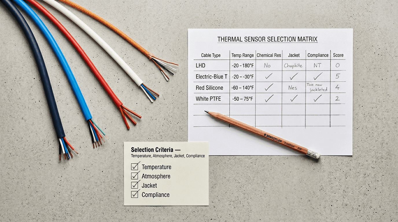
The six axes below are the dimensions on which the three sensors actually differ in a procurement decision. Nothing in any column makes one universally better — each sensor leads on a different axis, and the choice closes on which axes the deployment loads. Read it by the axis the application cares about most, not top to bottom.
| Axis | Thermal sensor cable | NTC thermistor | Thermocouple |
|---|---|---|---|
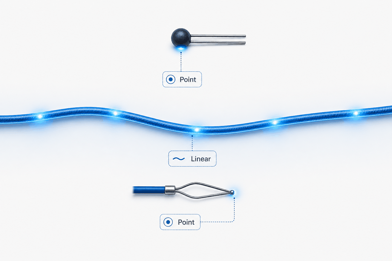
| Sensing geometry | Linear — senses along the entire installed length; the basis of linear heat detection. | Point — a single bead at one location. | Point — a single junction at one location. |
| Primary job | Trigger element — the sensor is itself the switch at the activation point. | Measurement element — reports a resistance the controller converts to temperature. | Measurement element — reports a voltage the controller converts to temperature. |
| Output signal | Dry-contact closing edge (metal-core) or temperature-dependent resistance fall (non-metal-core). | Resistance in the kilohm range on a nonlinear NTC curve. | Small DC voltage in the millivolt range from the Seebeck effect. |
| Controller dependency | Can trip a cut-off path autonomously; a dry-contact panel reads the close edge without firmware deciding. | Needs an ADC, curve linearisation and firmware to act on the reading. | Needs cold-junction compensation, amplification, an ADC and firmware to act. |
| Temperature range | Fixed activation grades (the six fixed-temperature classes used across this cable family: 68, 88, 105, 138, 170, 185 °C) plus custom set-points. | Standard parts typically used around −50 to +150 °C; special high-temperature assemblies may reach higher, with accuracy and long-term-stability trade-offs. | Very wide by type — roughly −200 to +1700 °C across type T, K, J, N, R and S. |
| Accuracy character | Set-point repeatability across a tolerance band (commonly ±5 to ±15 K); not a precision thermometer. | High resolution over a narrow band — the strongest point resolution of the three. | Moderate accuracy over a very wide range — range, not resolution, is the advantage. |
Two reading rules help. First, identify the job before the axis: a deployment that needs a switch reads the Primary job and Controller dependency rows first, and a deployment that needs a number reads the Temperature range and Accuracy character rows first. Second, let coverage geometry act as a hard filter rather than a preference — if the route is a line, the point sensors are out of the running for that job regardless of how they score on the other five axes, because a single bead cannot watch a tray. The accuracy axis sits last for trigger jobs and first for measurement jobs; it never settles the decision on its own.
Five Deployment Scenarios — Which Sensor the Application Asks For
The matrix above is read by axis. The reverse-lookup below is read by deployment. Five shapes cover most of the over-temperature and heat-detection traffic; each names the default sensor, the acceptable alternate when present, and the yellow flag that surfaces when the wrong type is forced onto the job.
When the Sensor Is Also the Trigger
The defining property of a thermal sensor cable — the one that the title points at and the one that separates it from the two thermometers — is that the sensing element and the switching element are the same object. A thermistor senses; a relay or a MOSFET switches; firmware links the two. A thermal sensor cable collapses that chain: the thermosensitive compound that senses the temperature is also the dielectric whose failure at the activation point closes (or opens) the circuit. There is no firmware in the link because there is no link to put firmware in.
That property buys two things a measurement sensor cannot. The first is independence from the controller. A measurement loop fails safe only while the controller is alive and correct; a trigger element fails toward its designed state when the temperature crosses the set-point, whether or not anything is reading it. The second is distributed coverage. Because the sensing-and-switching element runs the whole length of the cable, a single run watches an entire route, and any point along it that crosses the activation temperature acts on the circuit — the basis of linear heat detection, which a point sensor cannot reproduce without a dense array and software aggregation.
The trade is the other side of the same coin. A trigger element is not a thermometer — it reports that a threshold was crossed, not what the temperature is, and it does so within a tolerance band rather than to a precise reading. The internal construction that makes the trigger possible, layer by layer, is in the anatomy and trigger-physics walk-through, and the engineering index that frames the cable as a material-and-architecture object sits in the thermal sensor cable engineering note. When the job is to know a temperature, that trade is a dealbreaker; when the job is to act on an over-temperature event, it is the whole point.
Four A/B Decisions That Recur on RFQs
| Decision | Option A | Option B | Which fits |
|---|---|---|---|
| 01 · Coverage geometry Point sensor vs linear cable |
Point sensor (thermistor or thermocouple) — reads one known location precisely. | Linear thermal sensor cable — reads continuously along the whole route. | A when the risk is a single known hot spot the design can point at; B when heat or fire could appear anywhere along a tray, tunnel or conveyor and the run is too long for a point array to cover without blind spots. |
| 02 · Measure vs trigger Measurement loop vs autonomous trip |
Measurement element + controller — sensor reports, firmware decides and drives the actuator. | Trigger element (cable) in the cut-off path — the cable acts on the circuit by physics, no controller required. | A when the deployment needs a continuous reading for control or logging and the controller is reliably present; B when the deployment needs the trip to survive a hung MCU, corrupt firmware or a loose data wire. |
| 03 · Range vs set-point Wide-range measurement vs fixed-set-point trip |
Thermocouple wide-range measurement — reads a process from sub-zero into the hundreds or thousands of degrees. | Thermal sensor cable fixed set-point — triggers at one of the standard activation classes or a custom set-point. | A when the job is to know a process temperature across a wide span; B when the job is to act once a single over-temperature threshold is crossed and the precise value is not the deliverable. |
| 04 · Resolution vs threshold Continuous curve vs threshold event |
NTC thermistor continuous curve — high resolution over a narrow band for control and trending. | Thermal sensor cable threshold close — a clean event at the activation point, read by a dry-contact panel. | A when the host system samples and trends a temperature on an analog channel; B when the host system wants a discrete alarm or trip the moment the threshold is crossed. |
Layering the Three — They Coexist, They Don't Compete
The framing of "cable versus thermistor versus thermocouple" is useful for the selection decision and misleading for the system design. In a real system the three frequently appear together, each on its own layer. The measurement layer — a thermistor over a narrow band, a thermocouple over a wide one — gives the controller the continuous readings it needs to run the process, balance the cells or log the curve. The trigger layer — a thermal sensor cable — gives the system a physics-driven action that does not depend on the measurement layer being healthy. The two layers answer different questions, so adding one does not retire the other.
The EV battery pack in Scenario 04 is the clearest case: per-cell thermistors feed the battery management system, and a thermal sensor cable provides the independent cut-off that works when the BMS IC does not. The appliance cut-off path is the same pattern at smaller scale, examined in depth in the appliance safety note — the thermistor and firmware run the product, and the cable sits in series as the last layer that acts even when the software does not. Reading the sensor-type decision as "which one wins" loses the design; reading it as "which job needs which layer" keeps it.
Where the Sensor Choice Lands on the Spec Sheet
Once the sensor type is settled, the decision flows into the rest of the document chain. The map below shows where each downstream step picks up after the thermal sensor cable has been chosen over a point measurement sensor.
| Downstream step | How the sensor-type choice lands there |
|---|---|
| Selection framework — LHD vs TS | Once a thermal sensor cable is the sensor type, the framework's first step decides linear heat detection versus thermosensitive cut-off by application family. |
| Specification guide — Field 1 (cable family) | Field 1 of the spec sheet records the cable family; the sensor-type decision is the upstream choice that justifies opening a cable spec sheet at all rather than a thermistor or thermocouple datasheet. |
| Activation temperature selection | A trigger element needs a set-point; the standard six classes and the custom-set-point decision pick the activation temperature the trigger fires at. |
| One-shot vs resettable cutoff | For a cut-off-path deployment, the next architecture decision is whether the trigger is one-shot fusible or resettable PTC. |
| RFQ checklist | The RFQ states the sensor type and cable family in plain language, so a quote cannot quietly answer a cable enquiry with a point-sensor assembly or the reverse. |
Three sensors, two jobs, one question. Ask whether the deployment needs a number or a switch before asking which sensor is most accurate, and the choice between a thermal sensor cable, an NTC thermistor and a thermocouple usually closes on the first answer — then layer the measurement and the trigger rather than making them compete.
FAQ — Choosing Between TS Cable, Thermistor and Thermocouple
What is the fundamental difference between a thermal sensor cable, an NTC thermistor and a thermocouple?
The three sort into two jobs. NTC thermistor and thermocouple are measurement elements — each reports a value the controller converts to temperature and then decides what to do. A thermistor outputs a resistance in the kilohm range on a nonlinear NTC curve, with high resolution over a narrow band (standard parts typically around −50 to about +150 °C, with special high-temperature assemblies reaching higher). A thermocouple outputs a small DC voltage in the millivolt range from the Seebeck effect, with moderate accuracy over a very wide range (roughly −200 to +1700 °C across type T, K, J, N, R and S). A thermal sensor cable is a trigger element — the sensor is itself the switch. When the rated activation point is crossed, a metal-core cable presents a dry-contact closing edge that a linear heat detection panel reads without firmware deciding, while a non-metal-core cable presents a temperature-dependent resistance fall that a resistance-monitoring input reads the same way. The second fundamental difference is coverage geometry: thermistor and thermocouple are point sensors that read one location, while a thermal sensor cable is a linear sensor that reads along its entire installed length — the only one of the three that performs linear heat detection over a route.
When should I use a thermal sensor cable instead of a thermistor or a thermocouple?
Three deployment signals point to a thermal sensor cable rather than a point measurement sensor. First, when the coverage is a line rather than a point — fire or over-temperature detection along a cable tray, tunnel, conveyor, warehouse rack or long service gallery, where a point sensor cannot watch a run that may be tens to thousands of metres long and a linear cable triggers wherever along its length the activation point is crossed. Second, when the deployment needs an autonomous trip that does not depend on a controller — putting the sensor into the cut-off path so an over-temperature event still trips even if the microcontroller is hung or the firmware is corrupted, because the cable is a passive trigger while a thermistor or thermocouple needs a working controller to act on its reading. Third, when the question is whether a set-point has been crossed rather than what the precise temperature is right now. The anti-pattern is reaching for a thermal sensor cable when the job is continuous precise measurement for process control — a PID loop or a temperature-curve record — which is the work of a thermistor over a narrow band or a thermocouple over a wide one.
Can a thermistor or thermocouple do linear heat detection over a long cable route?
No — a thermistor and a thermocouple are both point sensors, each reading only the temperature at its own single location. Covering a cable tray or a tunnel with point sensors means distributing many of them along the route, wiring each back to a controller and aggregating in software, with cost and wiring complexity rising with length and blind spots remaining between the points. The whole value of a linear thermal sensor cable sits here: one cable senses continuously along its full length, any point crossing the activation temperature shows up at the panel, there are no gaps between points, and a single home run returns to the panel. This is why fire codes such as NFPA 72 in North America and EN 54-22 in Europe treat the line-type heat detector as its own detector category rather than as a string of point detectors. Point sensors suit a known single hot spot; a linear cable suits a route where heat or fire could appear at any position along the path.
If I choose a thermal sensor cable, do I still need a thermistor or a thermocouple in the system?
Usually yes — the three layer rather than compete. A common split has the thermistor or thermocouple carry the measurement-and-control layer (continuous reading, PID control, temperature-curve logging, per-cell battery monitoring) while the thermal sensor cable carries the independent-trigger and safety-backup layer (a controller-independent cut-off, or linear heat detection along a route). In an electric-vehicle battery pack a frequent combination is a per-cell thermistor for the battery management system measurement plus a thermal sensor cable for an independent cut-off that does not depend on the BMS IC keeping authority. On an industrial site a thermocouple reads the process temperature while a linear heat detection cable watches the route for fire. Choosing a thermal sensor cable is not replacing the other two; it is adding a physics-driven trigger chain alongside the measurement chain. Safety-conscious designs frequently put at least one passive trigger element in series with the active-sensing loop — belt plus braces.