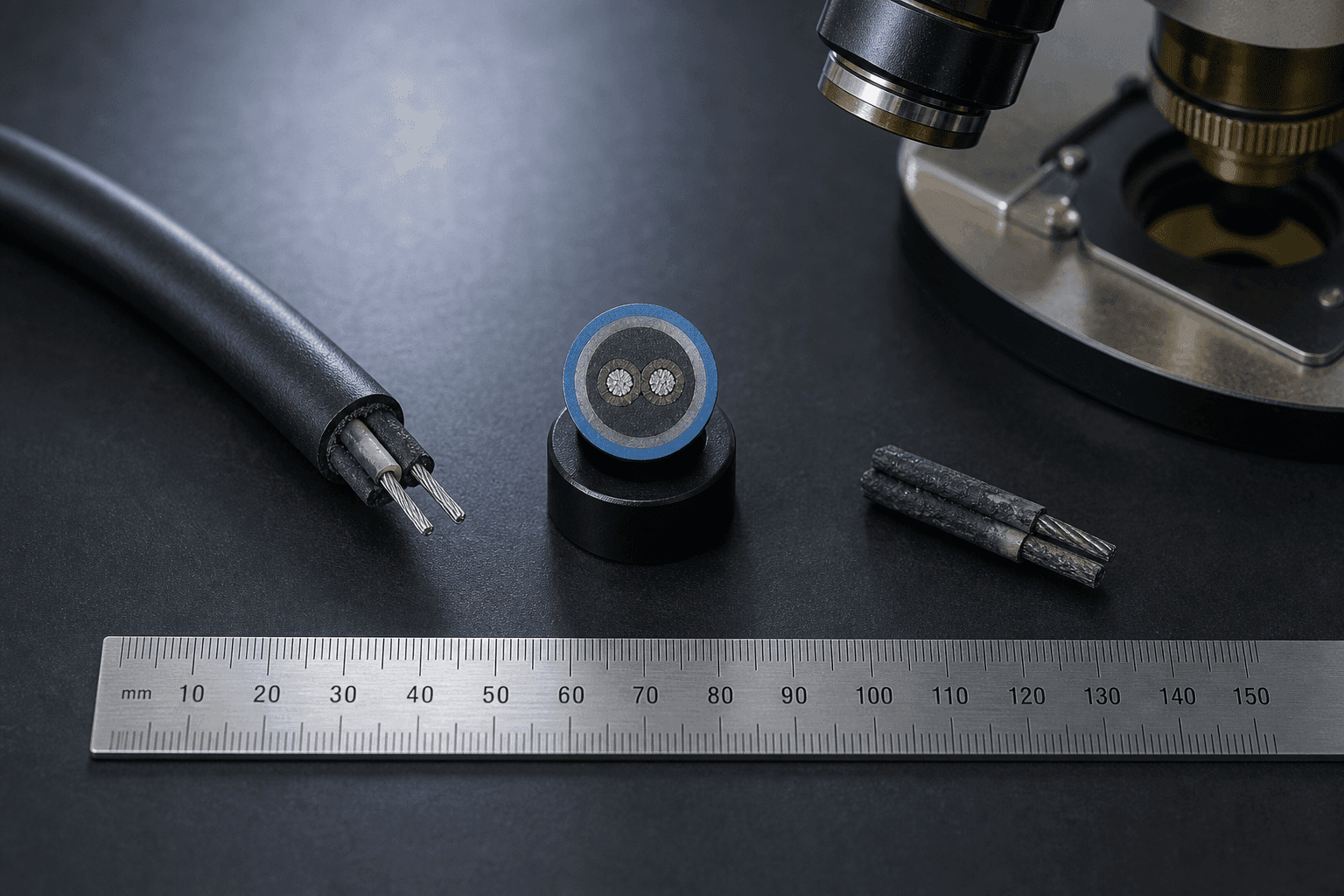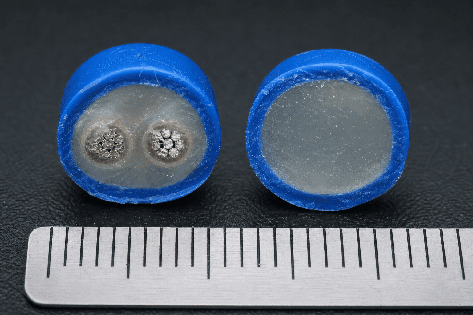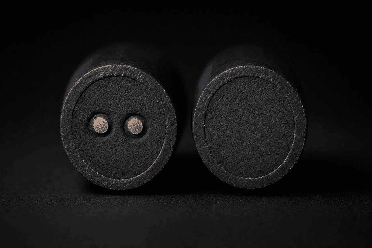
Two thermal sensor cables can carry the same printed activation point, the same outer diameter and the same jacket on the spec sheet, and still be two different architectures once the cross-section is on the bench. The substitution is the kind that quietly rewrites the panel reading at commissioning. A metal-core cable presents a sharp closing edge at the activation point and the dry-contact panel raises the alarm; a non-metal-core cable presents a smooth resistance fall and the same panel reads a fault instead. Nothing on the printed specification said which architecture would arrive, because Field 6 of most spec sheets — the geometry and cross-section row where architecture lives — leaves architecture implicit.
This note is the buyer-side decision matrix for that row. It extends the Architecture Axis section of the thermal sensor cable engineering index, where the two architectures are introduced as engineering objects and contrasted across five engineering dimensions. Here the same five dimensions are read from the procurement side: which architecture the deployment route is asking for, which signals tell you which architecture actually arrived, what changes downstream when the wrong architecture lands on the wrong panel, and which four trade pairs surface most often on RFQs. Architecture is also the row that Step 3 of the five-step selection framework handles in a single sentence; the matrix below is what that sentence unpacks into when the route survey is on the desk.
Why the Architecture Row Is Implicit on Most Spec Sheets
A typical thermal sensor cable spec sheet runs the twelve fields the specification guide walks one by one — cable family, activation temperature, working ambient, conductor alloy, jacket material, geometry and cross section, IP rating, mechanical envelope, termination strategy, compliance documents, per-batch QC and RFQ-ready wording. Architecture lives on Field 6 (geometry and cross section): the row carries the outer diameter and the construction family ("metal-core" or "non-metal-core"), but a thin spec often writes only the diameter and leaves the architecture line empty. Three neighbouring fields read against it without committing to either side. Field 4 (conductor alloy) names the conductor as "tinned copper" or "Ni80Cr20" without saying whether the conductor pair runs continuously along the active section. Field 8 (mechanical envelope) sets the bend radius, vibration class and crush rating the architecture has to survive without naming which architecture earns the envelope. Field 9 (termination strategy) records the panel make, the EOL value and the supervision current without forcing the cable's internal architecture to match. None of these on its own commits the supplier to either architecture, and the supplier's quote is free to substitute between them on cost grounds during a long RFQ.
The architecture choice changes three things downstream of the cable: the response window shape the panel reads, the termination hardware the install crew assembles and the bill-of-materials profile that decides who can quote at the requested unit price. Field 6 deserves to be written explicitly even when the project is comfortable with either architecture, because the document the AHJ or the third-party engineer reviews has to commit to one. The matrix that follows is the tool for writing that row before the substitution decides it.
The Five-Axis Decision Matrix
The five engineering dimensions below are the same ones the engineering index uses to introduce the two architectures, written here with a fourth column that names which deployment trigger should turn each axis from a comparison into a decision. Nothing in either architecture column makes one universally better; the choice closes on which dimensions the deployment route actually loads.
| Axis | Metal-core | Non-metal-core | Deployment trigger |
|---|---|---|---|
| Response window | Steep, panel-readable resistance step at the activation point. | Resistance falls with temperature on a smoother slope; activation edge is less abrupt than the metal-core step. | Dry-contact panel demanding a sharp closing edge → metal-core; analog-input panel sampling the resistance curve → either architecture works. |
| Mechanical robustness | Two thin metallic conductors can deform under heavy crush, vibration or sharp bend reversals. | No continuous metallic pair to deform; tolerates crush, vibration and bend cycling better. | Conveyor-adjacent, heavy-machinery or repeated bend route → non-metal-core; static cable-tray indoor route → metal-core acceptable. |
| Termination | Conductor-pair termination at each cable end; accepts standard EOL termination hardware. | Cable ends behave like a single resistor; fewer specialised fittings, simpler on-site termination. | Install crew under time pressure or unfamiliar with LHD EOL kit → non-metal-core; crew experienced with dry-contact LHD hardware → metal-core preferred for panel compatibility. |
| Cost band | Higher per-metre unit cost; the conductor alloy decision drives a meaningful share of the bill of materials. | Lower per-metre unit cost; per-installation cost depends on panel hardware and integrator familiarity. | Long route where per-metre cost dominates the BOM → non-metal-core; short route where panel hardware and integrator labour dominate → either architecture, compare delivered cost not per-metre. |
| Dry-contact panel fit | Reads cleanly on dry-contact LHD circuits that expect a sharp closing edge at activation. | Reads as a temperature-dependent resistor; fit depends on the panel's input topology and the integrator's familiarity. | Pre-installed dry-contact LHD fire alarm panel → metal-core default; custom analog-input or multi-channel temperature monitor → non-metal-core can adapt. |
Two reading rules help. Read the matrix top-down on the deployment trigger column first — the row whose trigger matches the route writes the architecture. Then read the matrix left-right on the chosen architecture column to confirm that the other four axes are acceptable side effects rather than dealbreakers. Cost band sits last, not first; per-metre price differences between the two architectures shrink on short routes and grow on long ones, and the install-side hardware cost frequently flips the delivered total.
Five Deployment Scenarios — Architecture by Route
The matrix above is read by axis. The reverse-lookup below is read by route. Five deployment shapes cover most of the procurement traffic on thermal sensor cable; each names the default architecture, the acceptable alternate when present, and the substitution that surfaces if the wrong choice arrives.
Substitution Detection — Three Signals When the Spec Sheet Goes Quiet
Field 6 staying implicit on the spec sheet is normal; the substitution arriving on the next reel is also normal. Three buyer-side signals tell you which architecture actually arrived, and the three signals are independent enough that two of them confirming the same answer is high confidence.
Termination Metallurgy × Architecture
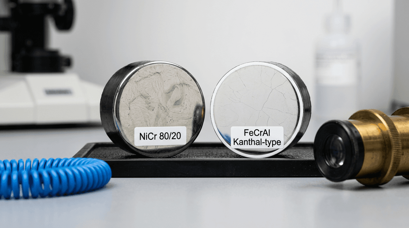
Architecture decides what terminates at each cable end, and the termination decides what the panel reads. Metal-core cable terminates two metallic conductors at each end with a conductor-pair termination kit: a dedicated dry-contact end-of-line device and a short tail to the panel input. The contact metallurgy between the conductor end and the panel-side hardware sets the long-term contact resistance. On ambient-rated cable that end is usually copper-based (tinned or nickel-plated copper); a high-temperature construction may bring a nickel-chromium end to the terminal, and paired against brass, tinned-copper or stainless each combination ages differently. Galvanic corrosion at the dissimilar-metal interface is a slow drift mechanism that surfaces after several years of service rather than year one, and how it is diagnosed and specified against is the subject of the termination metallurgy, aging and drift note. The single-conductor framework that the metal-core architecture inherits sits in the Ni80Cr20 versus Kanthal A1 conductor decision; the broader alloy treatment is in the conductor alloy framework for NiCr, FeCrAl and superalloy.
Non-metal-core cable terminates as a single resistor at each end — strip the jacket, terminate with standard heat-shrink and a moisture-rated wire connector, no LHD-specific EOL device on the procurement list. The panel side has to be an analog input that samples the resistance curve rather than a dry-contact input that expects a closing edge. Crossing the wires (metal-core into a single-resistor termination, or non-metal-core into a dry-contact EOL device) is the wiring mistake that surfaces during commissioning, not a property the cable itself can absorb. The architecture row on Field 6 and the termination row on Field 9 are tied through the panel input topology, and writing them coherently saves a commissioning revisit.
Four A/B Decisions That Recur on RFQs
| Decision | Option A | Option B | Which fits |
|---|---|---|---|
| 01 · Panel topology Dry-contact LHD panel vs analog-input temperature monitor |
Dry-contact LHD panel + metal-core cable — sharp closing edge at activation, discrete alarm trigger, dedicated EOL hardware. | Analog-input monitor + non-metal-core cable — temperature-dependent resistance curve, continuous reading, standard wire termination. | A when the panel side is already a dry-contact LHD circuit on a listed fire alarm system (typical on projects working under NFPA 72 or EN 54-22), or when a discrete alarm trip is the operational outcome the deployment was designed around; B when the host system already reads temperature on analog channels and the cable is one input among several. |
| 02 · Conductor alloy Metal-core + Ni80Cr20 vs metal-core + nickel-plated copper |
Ni80Cr20 conductor pair — flatter temperature-coefficient, sustained high-temperature service, oxidation-friendly long-term drift behaviour. | Nickel-plated copper conductor pair — lower per-metre cost, broader supplier list, adequate for the standard indoor and cable-tray ambient envelope that stays well short of the NiCr window. | A when sustained ambient runs above the copper window, the route has an oxidising or sulfidising atmosphere, or the activation tolerance band has to hold across a decade-long deployment; B when the route stays in the standard ambient envelope and the conductor cost is a meaningful share of the BOM. The deeper comparison sits in Ni80Cr20 versus Kanthal A1. |
| 03 · Termination hardware Non-metal-core termination kit vs metal-core EOL hardware |
Non-metal-core + standard wire connector — single-resistor termination, no specialised EOL device, lower crew training overhead. | Metal-core + dedicated EOL device — conductor-pair termination with a dry-contact EOL device, panel-compatible alarm signal, established panel ecosystem. | A when the install crew is unfamiliar with LHD EOL hardware, the panel side is an analog input, and the deployment schedule cannot absorb specialised training; B when the panel is a dry-contact LHD circuit with an established EOL hardware list and the crew has installed similar systems before. |
| 04 · Jacket × Architecture Fluoropolymer-jacket metal-core vs LSZH-jacket non-metal-core |
Fluoropolymer-jacket metal-core — chemical-plant rated, panel-compatible discrete trip, higher delivered cost. | LSZH-jacket non-metal-core — public-space code package, analog-input panel side, lower delivered cost. | A when the route is a chemical or petrochemical plant under chronic chemical exposure and the panel side is a dry-contact fire-alarm circuit; B when the route is a tunnel, metro or public building under code-driven smoke and halogen limits and the host system reads temperature on analog channels. The jacket-side detail sits in the jacket material decision matrix and the insulation-side detail in silicone vs PTFE vs fiberglass insulation. |
Where the Architecture Choice Meets the Rest of the Sheet
Field 6 does not end at the architecture row; it ties into three other rows on the same spec sheet and into two documents downstream of the sheet itself. The map below shows how the chosen architecture travels through each one.
| Downstream row or document | How the architecture choice lands there |
|---|---|
| Field 4 — Conductor Alloy | Metal-core requires a named conductor pair (tinned copper, nickel-plated copper, Ni80Cr20 or equivalent); non-metal-core leaves the conductor row inert because no continuous conductor runs the active length. |
| Field 8 — Mechanical Envelope | The bend radius, vibration class and crush rating filter the architecture set the deployment can carry; metal-core narrows the envelope, non-metal-core widens it. |
| Field 9 — Termination Strategy | The panel make, the EOL value and the supervision current the spec sheet records here decide which architecture the cable side has to deliver — a dry-contact LHD panel asks for a conductor-pair termination kit and a matched EOL device (metal-core); an analog-input monitor reads a single-resistor termination with standard heat-shrink and a moisture-rated connector (non-metal-core). |
| RFQ Field 5 — Architecture, Conductor Family, Insulation Family | The RFQ asks for the architecture family in plain language alongside the conductor and insulation families, so a cost-engineered substitution surfaces during quoting rather than at the commissioning loop test. |
| Sample evaluation — cross-section verification | The pre-PO sample evaluation's cross-section bench check reads the architecture off the slice; the resistance bench check then confirms the panel reading shape matches the panel datasheet expectation. |
The pattern is consistent across the five rows. The architecture choice on Field 6 is upstream; three spec-sheet rows and two downstream documents read against it. A clean choice at this stage lets the panel datasheet, the termination hardware list and the sample evaluation bench answer one question each — does the panel topology accept this architecture, does the EOL device match, does the cross-section sample show the architecture the spec sheet asked for — rather than re-litigate the architecture at commissioning.
Two architectures, five engineering axes, one row on the spec sheet. The cross-section is the document the panel actually reads; everything else on the sheet is a description of what the cross-section is allowed to be. Write Field 6 explicitly, name the architecture the panel topology requires, and let the downstream rows confirm the choice rather than discover it at commissioning.
FAQ — Metal-Core vs Non-Metal-Core Architecture
How do I tell if a quoted thermal sensor cable is metal-core or non-metal-core when the spec sheet does not say?
Architecture is the row most spec sheets leave implicit, so the buyer-side answer arrives from three independent signals rather than from the document. First, the cross-section sample — after receipt, cut a one-centimetre slice and view it under a loupe or bench microscope. A metal-core slice shows two metallic conductors embedded in the thermosensitive compound as two visible dots inside the cable cross-section, with the inner insulation and outer jacket around them. A non-metal-core slice shows a uniform compound block under the inner insulation, with no continuous metallic conductor pair in the active section. Second, the panel reading — with the cable powered, a four-wire milliohm reading across the cable terminals shows a steep resistance step at the activation point on metal-core cable (kilohm or megohm down to short-circuit below one hundred ohm), and a smoother resistance fall on non-metal-core cable (kilohm range descending with temperature). Third, the unit-price reverse-check — when same activation point and same jacket carry a spread on the order of one-and-a-half to two times between supplier quotes — a pattern we see often in the RFQs we have run — the lower quote is often the non-metal-core architecture rather than a simple manufacturing discount.
Why do many dry-contact LHD fire alarm panels expect metal-core thermal sensor cable?
Dry-contact linear heat detection panels read the cable as a switch — open-circuit at normal state, closed-circuit at activation. The panel input topology expects a sharp closing edge at the activation temperature, and it raises the alarm when the resistance across the loop crosses the threshold within milliseconds. Metal-core architecture supplies exactly that edge: the thermosensitive compound between the two metallic conductors collapses at the activation point and the conductor pair closes through it, presenting a panel-readable short. Non-metal-core architecture supplies a smooth temperature-dependent resistance fall instead — useful on an analog-input panel that samples the resistance value, but it does not cross a switching threshold the way a dry-contact panel expects. This is why many conventional dry-contact LHD installations — and most listed cable-panel systems sold into projects working under NFPA 72 in North America or EN 54-22 in Europe — are designed around metal-core cable: the closing edge is the alarm primitive the panel hardware was built to read. NFPA 72 and EN 54-22 themselves regulate fire alarm system performance and linear heat detector qualification rather than the cable's internal architecture; the metal-core default comes from the listed panel-cable system architecture, not from a clause that names it. Non-metal-core is appropriate when the panel side is an analog input or a custom PLC reading a temperature curve.
When is non-metal-core thermal sensor cable the right choice instead of metal-core?
Three deployment shapes default to non-metal-core architecture. First, routes with heavy crush, sustained vibration or sharp bend cycling — conveyor-adjacent runs, heavy-machinery rooms, routes whose installed bend reversals accumulate over hundreds of cycles per year — because the two thin metallic conductors of a metal-core cable can deform under cumulative mechanical stress, and the compound-only cross-section of non-metal-core tolerates the same mechanical envelope better. Second, projects where the install crew is unfamiliar with LHD end-of-line hardware or works under termination time pressure, because a non-metal-core cable terminates like a single resistor with standard heat-shrink and a wire connector rather than a dedicated EOL device. Third, long routes — thousands of metres of industrial cable run where per-metre unit cost dominates the bill of materials — because metal-core architecture carries the conductor alloy cost continuously along the active length while non-metal-core does not. The anti-pattern is treating non-metal-core as a generic cheaper substitute on a fire-alarm panel that expects a dry-contact closing edge: the panel will read fault instead of alarm and the substitution surfaces during commissioning.
Does the architecture choice affect the cable's termination metallurgy and the panel's EOL device?
Yes — architecture decides what terminates at each cable end, which in turn decides what the panel sees. Metal-core architecture terminates two metallic conductors at each end with a conductor-pair termination kit, typically a dedicated dry-contact end-of-line device and a short tail to the panel input. The long-term contact resistance is set by the metallurgy between the conductor end and the panel-side hardware — usually a copper-based (tinned or nickel-plated) end on ambient-rated cable, or a nickel-chromium end on high-temperature constructions, landed on brass, tinned-copper or stainless, and each pairing ages differently — with galvanic corrosion at the dissimilar-metal interface surfacing after several years of service rather than year one. Non-metal-core architecture terminates as a single resistor at each end — strip the jacket, terminate with standard heat-shrink and a wire connector, no LHD-specific EOL device required. The panel side has to be an analog input that samples the resistance curve, not a dry-contact input expecting a closing edge. Crossing the wires (metal-core into a single-resistor termination, or non-metal-core into a dry-contact EOL device) is a wiring mistake the panel notices during commissioning, not a property the cable itself can absorb.