A thermal cable can pass every electrical and thermal line on its datasheet and still be the wrong cable for your product. The activation point is dead on, the insulation resistance is high, the compliance paperwork is in order — and then it will not route around the last corner inside the housing without kinking, or the assembler pulls it snug under a clip and the reading drifts three months later. The specification the buyer scrutinised was the electrical one. The specification that actually failed was mechanical.
This note is about the mechanical envelope of a thermosensitive thermal cable: its outer diameter, its minimum bend radius, its crush and tensile limits, and the cut-length tolerance that turns a length of cable into a part. These are a separate specification axis from the activation set point, and in a compact OEM build they are the dimensions most often left implicit — assumed to be “fine” because the cable is small. The bend radius in particular is the single most under-specified figure we see on incoming RFQs, and it is the one most likely to cause a failure that surfaces long after the cable is buried in the assembly.
Why the Mechanical Envelope Is Its Own Specification
The activation temperature, its tolerance and the insulation behaviour describe what the cable does thermally. None of them tell you whether the cable physically survives being installed. A thermosensitive cable is not an inert wire — between its conductors sits a heat-sensitive compound engineered to collapse at a rated point, and the geometry of that compound and the conductor pair is exactly what a tight bend, a hard clamp or a firm pull disturbs. The layer-by-layer construction that makes the trigger work is covered in how a thermosensitive cable is built and triggers; the point here is that the same construction that senses heat is also mechanically delicate in ways an ordinary hook-up wire is not.
So the mechanical envelope earns its own place on the spec. It answers a different question from the thermal spec: not “when does it trip?” but “will it still trip correctly after it has been routed, clamped and lived in the enclosure for years?” Four dimensions do most of the work — diameter, bend radius, crush and pull — and the cut-length tolerance sits alongside them as the fifth.
How much of that scrutiny a given job needs varies. On a loose, open route with generous bends, no clamping and nothing that moves, the envelope is a quick sanity check rather than a design driver. It earns close attention in the opposite case — a compact housing, a clamped or flexing run, a tight corner, a vertical drop that has to carry its own weight — which is where a lot of OEM builds actually sit. The idea is to match the effort to the install, not to bolt a tight mechanical spec onto a cable that never sees mechanical stress.
Dimension 1 · Outer Diameter and the Cut-Out It Has to Clear
Outer diameter is the most visible mechanical figure and the easiest to under-check. It is quoted with a tolerance for a reason: a cable described as “3.5 mm” may actually run 3.2–3.8 mm across the reel, and the enclosure has to clear the top of that band, not the nominal. The classic failure is a cable sized to the nominal diameter that then will not pass the smallest gap on its route — a grommet, a slot in a bracket, the gap under a lid. As the appliance-integration rule of thumb goes, a 3 mm cable routed through a 2 mm gap never trips the way it was designed to, because it is already crushed before it senses anything.
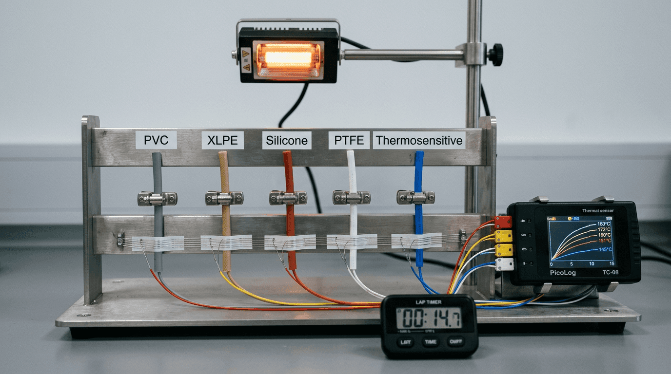
Diameter also quietly couples to the thermal side. A larger cross-section carries more thermal mass and more insulating wall, so a thicker cable generally takes longer to reach its activation point than a thinner one at the same set point — the mechanism behind that is the subject of how insulation shapes response time. The trade is straightforward: a thinner cable routes into tighter spaces and responds faster but is mechanically weaker; a thicker cable tolerates more mechanical abuse but needs more room and a larger bend radius. Choosing the diameter is choosing where on that trade you want to sit.
Dimension 2 · Minimum Bend Radius — the Headline Figure
Minimum bend radius is the tightest curve the cable can be routed around without the bend itself damaging it. It is almost never a fixed millimetre number in isolation; it is quoted as a multiple of the outer diameter, because a thicker cable needs a gentler curve. For a small jacketed thermosensitive cable, a static minimum bend radius in the region of 5 to 10 times the outer diameter is typical. Take a 3.5 mm cable rated at a 20 mm static minimum: that bend is about 5.7 times its diameter, and a 40 mm dynamic figure would be roughly 11 times. Those numbers are only a worked example — the real figures belong to the specific jacket, compound and conductor construction and have to be read off the datasheet.
What makes bend radius the dimension worth obsessing over is that violating it produces damage you usually cannot see. Bend a cable past its minimum and the strain concentrates at the apex of the curve: the jacket on the outside of the bend stretches and can craze or split, while the inside compresses and buckles. In a thermosensitive cable the internal consequence matters more — the compound between the conductors is deformed and the conductor spacing changes right at that point. That can shift the activation temperature locally, seed a stress concentration that fails early once thermal cycling starts, or open a moisture path into the core. None of that is visible from the jacket, and it typically does not announce itself until the cable is already in service.
Static versus dynamic — two different numbers
Bend radius comes in two flavours, and confusing them is a common and costly error. The static figure applies to a cable bent once during installation and then left alone — routed around a corner and clamped. The dynamic figure applies to a cable that flexes repeatedly in service: one that follows a lid, a hinge, or a moving assembly. The dynamic radius is the larger, gentler number, because repeated flexing fatigues the jacket and compound far faster than a single set bend. If your cable moves in use and you specified only the static radius, you specified for the wrong duty. Ask for both figures and the flex-cycle basis behind the dynamic one.
Dimension 3 · Crush and Compression — the Clamp and the Lid
A cable rarely fails from being bent alone; it fails from being bent and squeezed. Crush resistance — how much transverse force the cable takes before its cross-section deforms enough to matter — governs what happens under a cable tie pulled tight, a clip, the edge of a closing lid, or a bracket landed on the routing path. In a thermosensitive cable, crushing does the same thing a tight bend does: it changes the conductor spacing and disturbs the compound, only over a localised flat instead of a curve. The effect can be a shifted activation point or a latent weak spot.
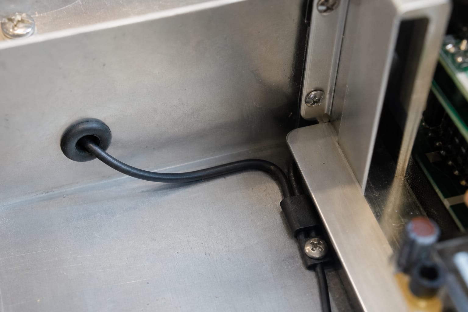
Two habits keep crush out of the failure log. First, treat clamping force as a spec, not a reflex — a cable tie zipped “until it stops” can exceed the crush limit of a small cable. Second, keep the cable off sharp edges and hard corners where the clamping force lands on a line contact rather than a broad one. Where a cable has to pass a pinch point, the enclosure should be designed around the cable's crush rating, not the other way round.
Dimension 4 · Tensile Strength and Strain Relief — the Pull
The last of the four mechanical dimensions is how much the cable can be pulled. Tensile strength, or the maximum recommended pull force, matters at two moments: during installation, when an assembler tugs a cable through a route, and in service, when a vertical run carries its own weight or a moving assembly tugs on it. Pull a thermosensitive cable beyond its limit and you can stretch and thin the conductors, disturb the compound, or unseat a termination — and terminations are already the part of a cable most prone to slow drift over years, as covered in why the drift is at the ends.
The practical answer is strain relief: anchor the cable near its termination so that any pull is taken by a clamp on the jacket, not by the conductors or the joint. A stated maximum pull force on the datasheet lets you size that anchor and brief the assembly line, rather than leaving “don't pull too hard” as an unwritten rule that the third shift never heard.
Dimension 5 · Cut-Length Tolerance — Where Mechanical Meets Logistics
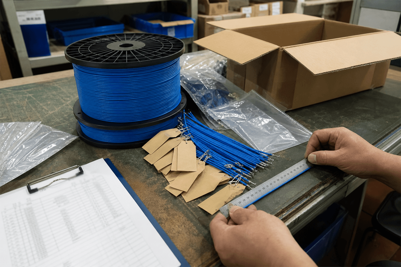
If the supplier cuts the cable to length rather than shipping a reel, the cut-length tolerance becomes a mechanical spec of the delivered part. A piece cut too short will not reach; a piece cut long has to be managed on the line. This sits at the boundary between the mechanical envelope and the procurement decision of who owns the cut, which is the subject of the cut-to-length versus spool note. For the mechanical spec, the point is simply that a cut length has a tolerance, and that tolerance belongs on the drawing when the part is defined by its finished length.
The Mechanical Envelope at Specification Scale
Pulled together, the mechanical envelope is five figures a specifying engineer can put on a drawing and a supplier can confirm against it:
| Mechanical parameter | What to specify | Why it decides the build |
|---|---|---|
| Outer diameter | Nominal + tolerance band (e.g. 3.5 mm, 3.2–3.8 mm) | Must clear the smallest cut-out and gap at the top of the band, not the nominal. |
| Minimum bend radius | Static, and dynamic if it flexes (as × OD or mm) | Every corner on the route must be larger than this; violating it deforms the core invisibly. |
| Crush / compression | Max transverse force or a rating | Governs clamp, tie and lid force; over-crush shifts activation like a tight bend. |
| Tensile / pull | Max pull force | Sizes the strain relief; over-pull thins conductors and unseats terminations. |
| Cut-length tolerance | ± on finished length (if cut to length) | A short piece will not reach; defines the delivered part against the BOM. |
Read the table down and a theme appears: every mechanical figure has a way of quietly reappearing as a thermal problem. An over-tight bend, an over-hard clamp, an over-hard pull — each one disturbs the conductor spacing or the compound, and each one can move the activation point or seed an early failure. That coupling is why the mechanical envelope is not a lesser spec than the thermal one; it is the spec that decides whether the thermal one survives the enclosure.
The electrical spec says what the cable does on the bench. The mechanical envelope says whether it still does it after someone routed it, clamped it and closed the lid. Spec both, or you have only specified half the cable.
Getting the Mechanical Envelope Onto the RFQ
Most mechanical failures trace back to a spec that named the activation point precisely and left the mechanical figures implied. The fix is to name them. On the RFQ, alongside the activation set point and tolerance, state the outer diameter and its tolerance; the minimum bend radius, marked static or dynamic; the crush rating for any clamped routing; the maximum pull force; and, for cut pieces, the length tolerance. Add the operating temperature range so those figures are read at the real service temperature — jackets stiffen in the cold and soften in the heat, and a bend radius that is fine at 25 °C is not automatically fine at −40 °C. The full field-by-field structure lives in the RFQ checklist, the mechanical envelope sits as Field 8 of the thermal sensor cable specification guide, and it is one of the OEM verification items behind using a thermosensitive cable as the last line of appliance safety.
The single most useful step a buyer can take is to send the enclosure drawing with the RFQ and ask the supplier to confirm the cable's mechanical envelope against it — smallest gap, tightest corner, clamp points, any flexing. That turns the mechanical spec from an assumption into a checkable acceptance criterion, and it is far cheaper to resolve on a drawing than in a pilot build.
Closing Note
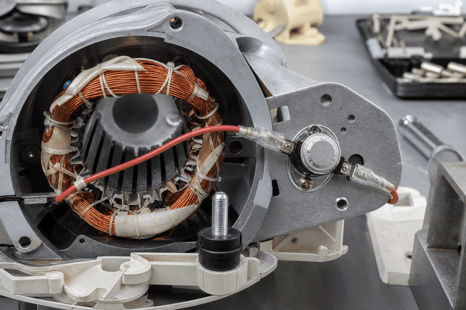
A thermal cable is chosen on its activation point and qualified on its mechanical envelope. If you are fitting one into a compact housing — a small appliance, a battery pack, a motor slot, a sealed instrument — send us the enclosure drawing and the routing constraints along with the thermal target. We will come back with an outer diameter, a static and dynamic bend radius, crush and pull figures, and a draft mechanical spec line to sit beside the activation spec — turnaround scheduled subject to project scope and engineering review. Start a conversation.
FAQ — Bend Radius and the Mechanical Envelope
What is the minimum bend radius of a thermosensitive thermal cable?
Minimum bend radius is the tightest curve a cable can be routed around without the bend damaging it, and it is normally quoted as a multiple of the cable's outer diameter rather than a fixed millimetre figure. For a small jacketed thermosensitive cable a common range is roughly 5 to 10 times the outer diameter for a fixed (static) install, with a larger figure for a cable that will flex repeatedly. As a worked example, a 3.5 mm cable rated at a static minimum bend radius of 20 mm is bending at about 5.7 times its diameter, and might carry a 40 mm figure — around 11 times — for repeated flexing. Read the specific figure, and whether it is static or dynamic, off the datasheet, because it depends on the jacket, the compound and the conductor construction, not on the diameter alone.
What happens if you bend a thermal sensor cable tighter than its minimum bend radius?
Bending tighter than the minimum radius concentrates strain at the apex of the bend. On the outside of the curve the jacket stretches and can craze or split; on the inside it compresses and can buckle. In a thermosensitive cable the more important consequence is internal: the heat-sensitive compound between the conductors is deformed, and the spacing between the conductor pair changes at that point. That can shift the activation point locally, create a stress concentration that fails early under thermal cycling, or in the worst case leave a partial short or an ingress path for moisture. The damage is often invisible from the outside and does not show up until the cable is in service, which is why the bend radius is a build-time acceptance check, not a suggestion.
What is the difference between static and dynamic bend radius?
Static bend radius applies to a cable that is bent once during installation and then stays put — routed around a corner inside an enclosure and clamped. Dynamic bend radius applies to a cable that flexes repeatedly in service, such as one that follows a moving door, a hinge or a reciprocating assembly. The dynamic figure is the larger of the two — a gentler bend — because repeated flexing fatigues the jacket and the compound far faster than a single set bend. If your application flexes the cable, specifying only the static radius is a common and expensive mistake; ask the supplier for the dynamic figure and the flex-cycle basis behind it.
Does cable diameter affect the activation temperature or response time?
Diameter does not set the activation temperature — that is fixed by the compound formulation — but it does influence response time and mechanical fit. A thicker jacket and larger cross-section add thermal mass and insulation, so a larger cable generally takes longer to reach its activation point than a thinner one at the same set point. The larger cable is also mechanically tougher and has a larger minimum bend radius. So diameter is a trade: a thinner cable routes into tighter spaces and responds faster, while a thicker cable tolerates more mechanical abuse. The activation set point and its tolerance are specified separately from the mechanical envelope.
How do I route a thermal cable in a tight appliance enclosure?
Start from the mechanical envelope, not the electrical spec. Confirm the outer diameter and its tolerance clear the smallest cut-out and gap the cable has to pass through, with margin — a 3 mm cable forced through a 2 mm gap is crushed before it ever senses anything. Check that every corner on the routing path is larger than the cable's minimum bend radius, and use the dynamic radius wherever the cable flexes. Avoid clamping or cable-tying hard enough to exceed the crush limit, keep the cable off sharp edges, and make sure the routed cable is still thermally bonded to the surface it is meant to sense rather than held away from it. Where the housing is genuinely too tight for the standard cable, a smaller-diameter grade may exist, but confirm its response time and mechanical ratings before substituting.
What mechanical specifications should I put on an RFQ for OEM thermal cable?
Name the mechanical envelope explicitly rather than assuming it. At minimum: outer diameter with a tolerance; minimum bend radius, stated as static and, if the cable flexes, dynamic; crush or compression resistance for any clamped or lidded routing; tensile strength or a maximum pull force for installation and any vertical run; and, if the supplier is cutting the cable, the cut-length tolerance. Add the operating temperature range so the mechanical figures are understood at the real service temperature, since jackets stiffen in the cold and soften in the heat. Asking the supplier to confirm these against your enclosure drawing turns the mechanical spec from an afterthought into a checkable acceptance criterion.