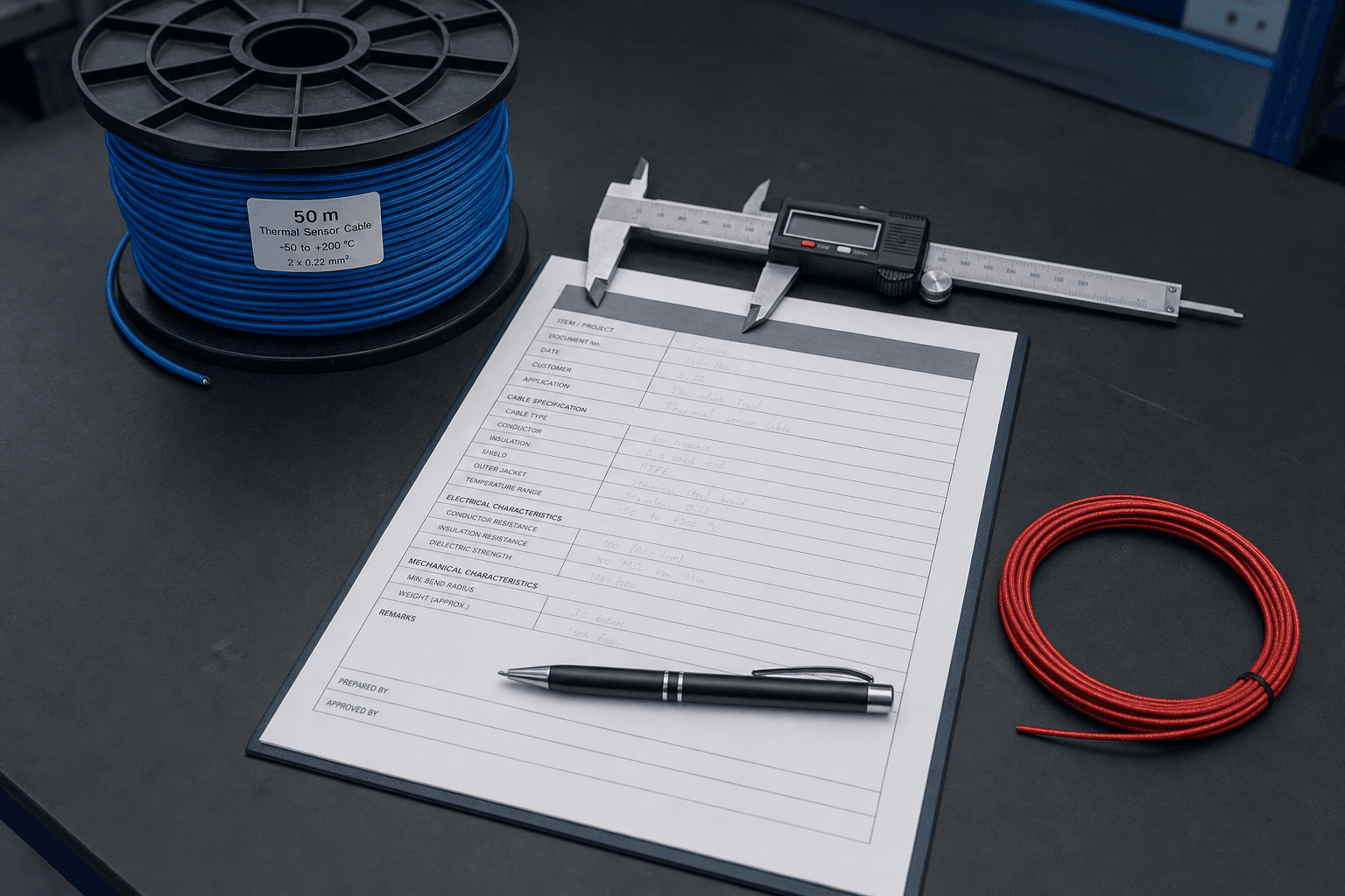
Field 2 of a thermal sensor cable specification sheet asks for one number — the activation temperature. The number itself is short. The decision behind it is not. Activation temperature selection for thermal sensor cable is the place where the spec sheet either lines up with the route the cable will live in, or quietly takes on a nuisance-alarm problem and a procurement problem at the same time. That single number is also the set point of a fixed-temperature detection mode — the activation class only makes sense once you have decided the cable should trigger on an absolute temperature rather than on a rate of rise.
This page extends that one field into a full decision path. The companion engineering reference is Field 2 of the thermal sensor cable specification guide; the procurement counterpart is Field 4 of the RFQ template. The cable family this discussion applies to — LHD for linear heat detection and TS for in-device thermosensitive cut-off — is set out on the cable series page.
When the Decision Matters, and When It Quietly Defaults
Not every project needs a long deliberation on Field 2. The decision earns time when the route puts pressure on the activation class; on benign routes the standard six does most of the work on its own.
the working ambient sits close to the nearest standard class, the alarm-response window is narrow, the cable feeds a fire-protection or OEM safety review, or the project target temperature falls between two of the six.
the route ambient sits 20-30 K below the nearest class, the deployment has used the same class on previous shipments without nuisance alarms, and second-source flexibility is more valuable than tighter tolerance.
the working-ambient calculation in Field 3 of the spec guide, the failure-mechanism walk-through in the engineering reference, or sample evaluation. Selection sets the target; verification confirms the cable hits it.
The boundary is useful. A clean activation-class decision does not prove how the cable behaves at year ten — that question belongs to the thermal sensor cable engineering reference. What this page does is land Field 2 in a way the engineering reference can build on without re-opening the choice.
The Standard Six — What Each Class Was Sized For
The six standard activation points a thermal sensor cable buyer meets most often are 68, 88, 105, 138, 170 and 185 °C, with a default tolerance band of ±15 K. The six were not picked arbitrarily — each maps to a deployment envelope where the working ambient and the activation class sit a comfortable headroom apart.
| Class | Deployment envelope | Ambient peak the class is sized for (illustrative) | Headroom this class accepts |
|---|---|---|---|
| 68 °C | Cold-storage and refrigerated rooms. | Around 30-40 °C in service, lower during cold cycle. | Wide; class sits well above any non-fault ambient. |
| 88 °C | Office and data-center ceilings. | Around 55-65 °C under hot-aisle drift. | Comfortable on cold-aisle returns; tighter on hot-aisle ceilings. |
| 105 °C | Indoor industrial. | Around 70-85 °C near heated equipment. | Comfortable; the spec-guide example of 80 °C ambient with 105 °C activation lives here. |
| 138 °C | Warehouses with summer ambients and outdoor metal roofs. | Around 95-115 °C under summer roof heat. | Adequate on shaded roofs; tighter under direct sun. |
| 170 °C | Tunnels and process plants. | Around 130-150 °C near hot process streams. | Class is sized for the steady-state heat of these routes. |
| 185 °C | Turbine halls and high-bay refineries. | Around 140-160 °C near combustion or refining equipment. | Class accepts the upper-end industrial ambient with a working headroom. |
The ambient figures above are typical envelopes, not contractual values; what the deployment actually sees depends on the route survey. Two patterns surface across the six. First, the class spacing is uneven on purpose — the gaps reflect industrial envelopes that cluster naturally rather than a uniform interval. Second, the deployment label is a guideline; if the route survey gives an ambient peak that lands on the boundary between two classes, the decision moves to the headroom rule.
The Headroom Rule, Then the Class
The fastest way to land Field 2 wrong is to pick the activation class before the working ambient is settled. The activation class is supposed to sit above the highest sustained working ambient by a headroom of roughly 20-30 K for most LHD applications — including seasonal peaks and adjacent equipment thermal drift. A class chosen below that headroom will eventually nuisance-alarm; a class chosen far above it will leave the route under-protected.
Two short examples make the geometry visible. The first is the comfortable case — the example built into the spec guide:
The same ambient against the next class down tells the opposite story:
80 °C ambient with a 105 °C class sits 25 K above the working ambient, and a ±15 K tolerance window stays out of the nuisance zone. 80 °C ambient with an 88 °C class sits only 8 K above the ambient — the same ±15 K window now extends down past the ambient, and the class that looked fine on paper will not stay quiet for long.
Both cases use classes from the standard six. The difference between them is the headroom calculation, not the catalogue. Field 3 of the spec guide walks the working-ambient rule on the engineering side; this page assumes that calculation is already done and addresses what happens after it. For how to establish the working-ambient figure itself — what it includes and how to survey a route rather than quote a nameplate — see where it lives is not where it trips.
When to Leave the Standard Six
The standard six covers most projects but not all. A custom activation temperature set-point earns its cost when the closest standard class is more than half a tolerance band off the project target, or when the route survey produces a number that does not align with the six. Three situations recur:
- EV battery packs around 95 °C. 95 °C technically falls inside the ±15 K window of the 88 °C class, but EV thermal-runaway verification typically demands a ±5 K window — and a ±5 K band around 88 °C reaches only 93 °C, short of the target. A custom set-point at the pack threshold is the cleaner answer.
- Motor windings around 130 °C matched to IEC Class B insulation. The target sits between 105 and 138 °C and is driven by the host product's insulation class rather than the cable catalogue.
- Process equipment with a documented set-point — for example, a specific bearing cap or a chemical reactor — where the equipment vendor defined the activation temperature long before the cable was sourced.
Custom is available across a wide make-to-order range; the typical engineering window extends to the upper end of the standard six, with the high-end ceiling and tighter tolerance taken on a per-project basis. Two costs follow custom into the project: longer engineering review on the supplier side, and a narrower supplier list — not every factory holds tight tolerance on a non-standard temperature. The third cost, longer sample lead time, is the practical consequence of the first two.
Tolerance Band — When Tightening Buys Something
The activation temperature tolerance band on a thermal sensor cable spec sheet is the line item most sheets forget. The default on the standard six is ±15 K; the question is whether the route gives the deployment a reason to tighten it to ±10 K or ±5 K.
The tolerance band tracks three conditions: headroom, route response window, and verification window. None of the three is a simple threshold — they shape the decision together.
- Headroom. A route with comfortable headroom — say 25 K between ambient peak and activation class — can usually tolerate ±15 K without nuisance alarms. A route whose ambient peak sits close to the class is the case where ±10 K starts to earn its cost.
- Route response window. Open-ceiling spaces and atmospheric cable trays under shade have generous alarm-response windows; the activation point does not have to land within a few degrees to be useful. Narrow-window routes — confined hot zones, cyclic-duty equipment, fast-moving extract air — are where tighter tolerance starts to look reasonable.
- Verification window. When the buyer's sample evaluation or commissioning bench tests have a tight acceptance window, the tolerance on the spec sheet has to fit through it. The activation-spread test in the nine-parameter QC checklist shows how the bench-side window relates to the spec-sheet band.
Two anti-patterns surface here. The first is tightening the tolerance with no route reason: the supplier list narrows, the QC effort on each batch rises, and the deployment sees nothing for either. The second is leaving the tolerance unstated on the RFQ, which lets the supplier price against the loosest tolerance their process supports. The cleanest pattern is to write a band that the headroom and the route response window justify, then let the verification window confirm the choice rather than override it. How tight a band is realistically achievable on a given class, and what tightening costs on the factory side, is the subject of the companion note on custom activation tolerance.
Four Layers, Four Different "Activation Numbers"
One phrase — activation temperature — sits on four different documents in slightly different forms. Reading them as the same number is a common procurement mistake; reading them as related but distinct numbers keeps the selection clean.
Standard Class
the catalogue numberContains — One of 68, 88, 105, 138, 170 or 185 °C with a default ±15 K tolerance band.
How a buyer reads it — Pick the class whose headroom over the working ambient sits in the 20-30 K window; tighten the band only when the route gives a reason.
Nominal on the Batch
what the report writesContains — The class and tolerance band as printed on the outgoing batch inspection report — for example, 88 °C ±15 K — alongside the measured value for that batch.
How a buyer reads it — The measured value should land inside the band agreed in the RFQ; see how to read the batch inspection report for the row-by-row check.
Bench Spread
three samples in an oil bathContains — The activation-point spread across three 1 m samples per batch in a controlled-temperature oil bath, ramped slowly toward the class; the test method behind the nominal value.
How a buyer reads it — The spread is the production-line bound on the band the spec sheet can promise; see the activation-point spread parameter for the method.
In-Service-Aged
what year-ten readsContains — The activation point after years on the route — oxidation, cycling fatigue, moisture ingress and dielectric drift each move it by a different mechanism.
How a buyer reads it — Selection should leave room for the aging mechanisms described in the engineering reference; the specific direction and time horizon belong to the route, not to a single number.
The four layers are linked by the same word but are not interchangeable. Selection lands the standard class and tolerance band; the batch report carries the nominal value for one shipment; the bench spread is the production-line method behind that nominal; the in-service-aged value is what the route eventually returns. A clean spec sheet is one where each layer can be traced to the layer above it without contradiction.
Three Comparisons That Shape the Decision
Where Selection Meets the Rest of the Sheet
Selection does not end at Field 2; it ties into three downstream documents. The map below shows how the chosen activation class travels through each one:
| Downstream document | How the selection lands there |
|---|---|
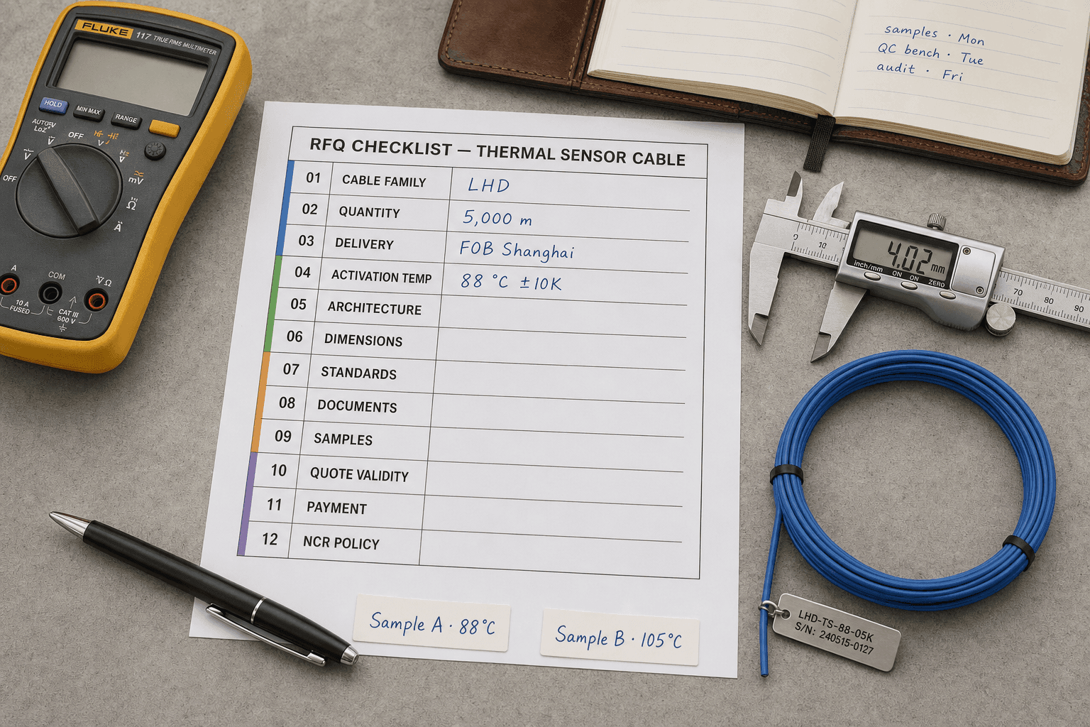
| RFQ Field 4 — Activation class & tolerance band | The class chosen here becomes the RFQ line, together with the tolerance band and the working ambient on a separate row. Once the selection here is settled, the RFQ template gives the wording. |
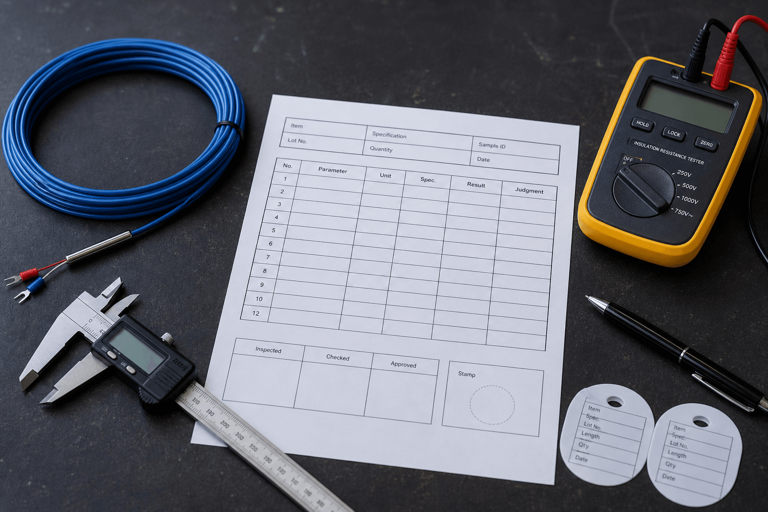
| Batch inspection report row 5 | The measured activation value on each batch is read against the class and tolerance band agreed in the RFQ — not against a generic threshold. |
| Activation-point spread test (QC parameter 1) | The factory bench method that produces the measured value. The spread on three 1 m samples is the production-line bound on the tolerance band the spec can promise. |
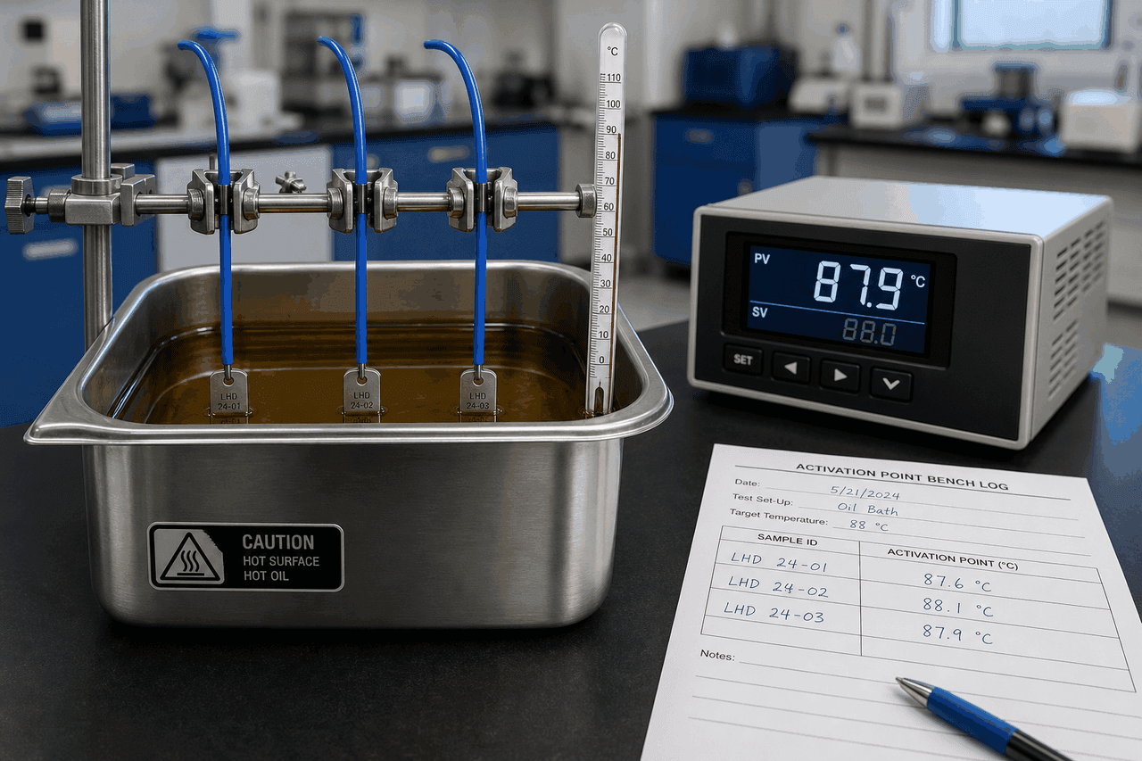
| Supplier evaluation — stage 2 sample bench test | A 30 cm offcut in a controlled-temperature oil bath, ramped at roughly 1 K per minute toward the rated activation point; the buyer-side counterpart to the factory spread test. |
The pattern is consistent: how to choose the activation temperature for a thermal sensor cable is the upstream decision; the four downstream documents read against the class and tolerance band the selection produced. A clean decision at this stage is what lets each downstream check answer a precise question instead of a vague one.
The number in Field 2 is short. The headroom calculation in Field 3, the tolerance band on the RFQ line, the measured value on the batch report and the bench spread on the production line all read against it. Choose it from the route, write it from the choice, and let the downstream documents confirm the choice rather than carry it.
FAQ — Activation Temperature Selection
How do I choose the activation temperature for a thermal sensor cable?
Start with the route, not the catalogue. Settle the working ambient first — the highest sustained temperature the cable will live at on this route, including seasonal peaks and adjacent equipment drift. The activation class sits above that envelope by a headroom of roughly 20 to 30 K for most LHD applications, so the cable does not nuisance-alarm on a hot summer afternoon. Once the activation class is fixed, the tolerance band follows the headroom: a route with comfortable headroom can usually tolerate ±15 K; a route whose ambient peak sits close to the class with little nuisance margin is the case where ±10 K or ±5 K starts to earn its cost. Custom set-points become reasonable when the closest standard class is more than half a tolerance band off the target temperature; otherwise the standard six is faster, cheaper and easier to second-source.
What are the six standard activation temperatures for thermal sensor cable and which fits my project?
The six standard activation classes are 68, 88, 105, 138, 170 and 185 °C, with a default tolerance band of ±15 K. Each class is sized for a deployment envelope: 68 °C for cold-storage and refrigerated rooms; 88 °C for office and data-center ceilings; 105 °C for indoor industrial; 138 °C for warehouses with summer ambients; 170 °C for tunnels and process plants; 185 °C for turbine halls and high-bay refineries. The fit follows from the route ambient and the headroom rule rather than from the catalogue alone: a route whose highest sustained ambient sits about 20 to 30 K below the class is comfortably in range. A route whose target temperature sits between two classes is the case where a custom set-point is worth pricing.
When should I specify a custom activation set-point instead of one of the standard six?
A custom set-point earns its cost when the closest standard class is more than half a tolerance band off the project target, or when the project's verification window is tighter than the band a standard class can absorb. Typical examples are EV battery packs around 95 °C — where a ±5 K thermal-runaway verification around the 88 °C class reaches only 93 °C, short of the target; motor windings around 130 °C matched to Class B insulation; or specific process equipment with a documented set-point that does not align with the standard six. Custom also widens beyond the standard six toward the upper end of the make-to-order range, with tighter tolerance available on request. The trade-offs are real: longer engineering review on the supplier side, longer sample lead time, and a narrower supplier list because not every factory can hold tight tolerance on a non-standard temperature. The standard six remains faster, cheaper and easier to second-source when the project target lands inside a tolerance band of one of the six.
What tolerance band should the activation temperature carry — ±5, ±10 or ±15 K?
The tolerance band follows the headroom between the working ambient and the activation class, not the supplier's catalogue. A route with comfortable headroom and a wide alarm-response window can usually tolerate ±15 K. A route whose ambient peak sits close to the class, or whose nuisance margin is narrow, is the case where ±10 K starts to earn its cost; ±5 K typically belongs to projects where the verification window itself is tight or where the standard class is one step away from the target. Tightening the band without a route reason is expensive on two sides: the supplier list narrows because not every factory holds tight bands, and the QC effort on each batch goes up — neither of which the deployment can see if the headroom was already generous. Tighter is something the deployment has to ask for, not something the spec sheet tightens by default.