Two thermal sensor cables with the same printed activation temperature can drift apart by 20 K after five years on the same circuit. One alarms a minute earlier than the other. One never alarms because its NiCr conductor has been stripped of chromium by an atmosphere nobody documented during procurement. The reason is rarely on the data sheet. It lives in the materials, in the internal architecture and in the failure modes nobody asked about when the cable was specified.
This page is an engineering desk's index for thermal sensor cable engineering. It does not re-state the alloy comparison, the insulation comparison or the oxidation walk-through that already exist as dedicated engineering notes. It is the navigation layer that ties them together (a three-axis view of materials, internal architecture and time-domain failure), so a buyer or a third-party engineer can find the right deep dive without reading the whole site. If the question on your desk is why two cables with the same spec behave differently in service, start here and follow the link that matches the part of the answer you need.
The structure is intentional. Thermosensitive cable design fundamentals split cleanly along three axes: which layer of the cable you are looking at, how the layers are stacked, and how each of them changes over the deployment lifetime. Every engineering note on this site lives at the intersection of two or three of those axes. This page maps the intersections so the right note surfaces against the question you are actually asking.
The Three Axes of Thermal Sensor Cable Engineering
A thermal sensor cable is a stack of materials with a printed activation point on the outside. Two cables with identical activation points can have completely different stacks underneath, and the behavioural differences only show up at the intersections of three axes. Almost every engineering question worth asking about a thermal sensor cable is a question about one of these three axes or about the intersection between two of them.
Materials axis — the five layers inside the cable
From the inside out: the conductor alloy, the thermosensitive compound, the inner insulation, the outer jacket and the termination metallurgy. Each layer is a discrete engineering decision with its own data sheet, its own QC procedure and its own failure mechanism. A specification that names five materials and leaves the architecture and the time axis to interpretation is a specification that survives a procurement review but loses a field engineer's review.
Architecture axis — how the layers are stacked
The same five materials can be assembled into a metal-core or a non-metal-core cable, and the choice changes the response sharpness, the mechanical robustness and the termination simplicity. Architecture is the axis a spec sheet most often leaves implicit, and the axis that most often gets substituted on cost grounds during a long RFQ.
Time axis — why the activation curve moves over ten years
None of the four active material layers stays still over a deployment lifetime. Four headline aging families surface against those layers — oxidation (with sulfidation and halogen attack as atmosphere-driven variants), cycling fatigue, moisture ingress and dielectric drift — each moving the activation curve by a different mechanism on a different time horizon. A thermal sensor cable failure mechanisms overview is essentially a tour of the time axis, layer by layer.
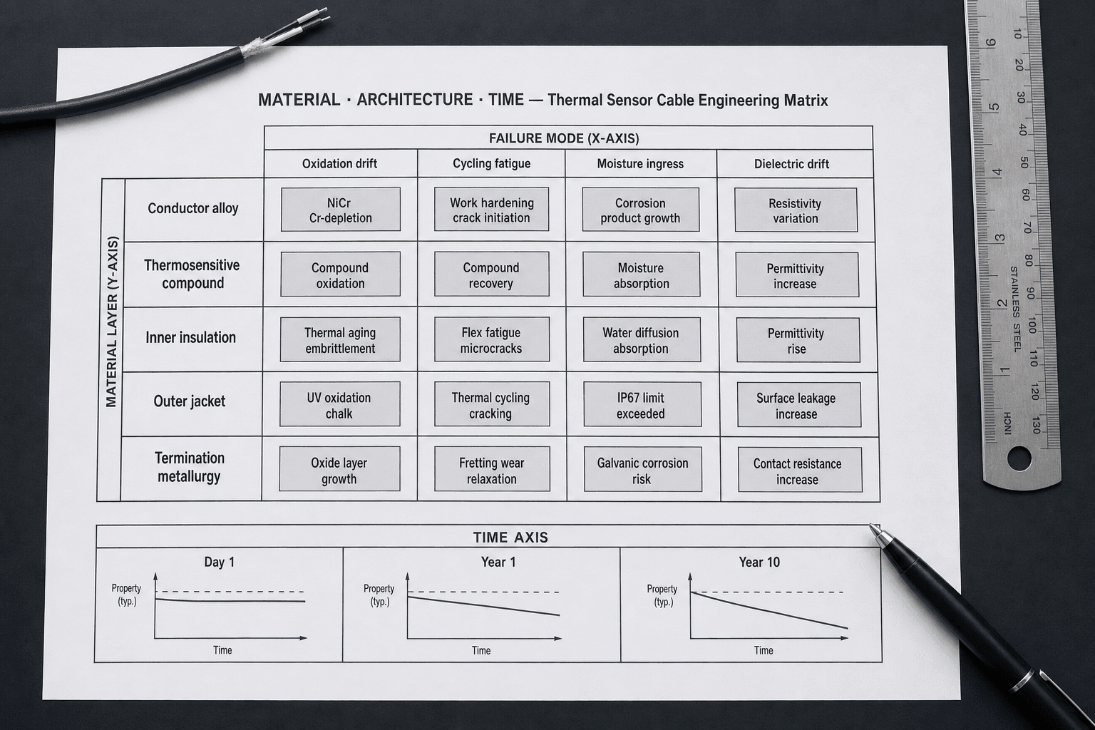
Materials Axis — Thermal Sensor Cable Materials Engineering, Layer by Layer
Thermal sensor cable materials engineering is the discipline of choosing five layers so they survive the route the cable will live in. Each layer has its own engineering note on this site. This section is the index: what the layer does, what the decision turns on, and which deep dive carries the property data.
Conductor alloy
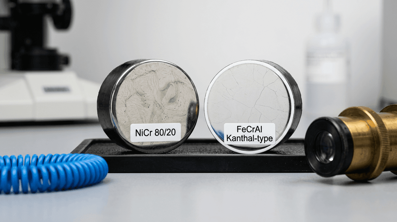
For ambient-rated LHD and TS cable, the conductor is a copper-based pair (tinned-copper or nickel-plated copper) and the decision is closed on one row of the spec sheet. The conductor question opens up when the cable runs at sustained ambients above roughly 150 °C, when the conductor itself is expected to carry meaningful heat, or when the cable uses a resistance-wire sensing topology. In that band, three alloy families dominate: nickel-chromium (typically Ni80Cr20), iron-chromium-aluminium (typically Kanthal A1) and the nickel-superalloy family. Each has a different resistivity, a different temperature-coefficient linearity and a different long-term drift behaviour in real atmospheres. The decision between the first two sits in the Ni80Cr20 versus Kanthal A1 conductor decision; the broader framework spanning all three alloy families is in the conductor alloy framework for NiCr, FeCrAl and superalloy.
Thermosensitive compound
The compound is the active sensing element. Two property axes matter: the temperature at which its resistance collapses (the activation point) and the steepness of the collapse (how cleanly the panel reads the alarm). A formulation that gives a sharp resistance step at 105 °C is a different chemistry from one that gives a sharp step at 170 °C, and neither formulation is automatically derived from the printed activation number on the jacket. The compound is also the layer most sensitive to cycling fatigue and moisture ingress over the deployment lifetime. The layer-by-layer thermosensitive cable anatomy and trigger physics walk-through covers what the compound is doing at the molecular level when the cable activates.
Inner insulation
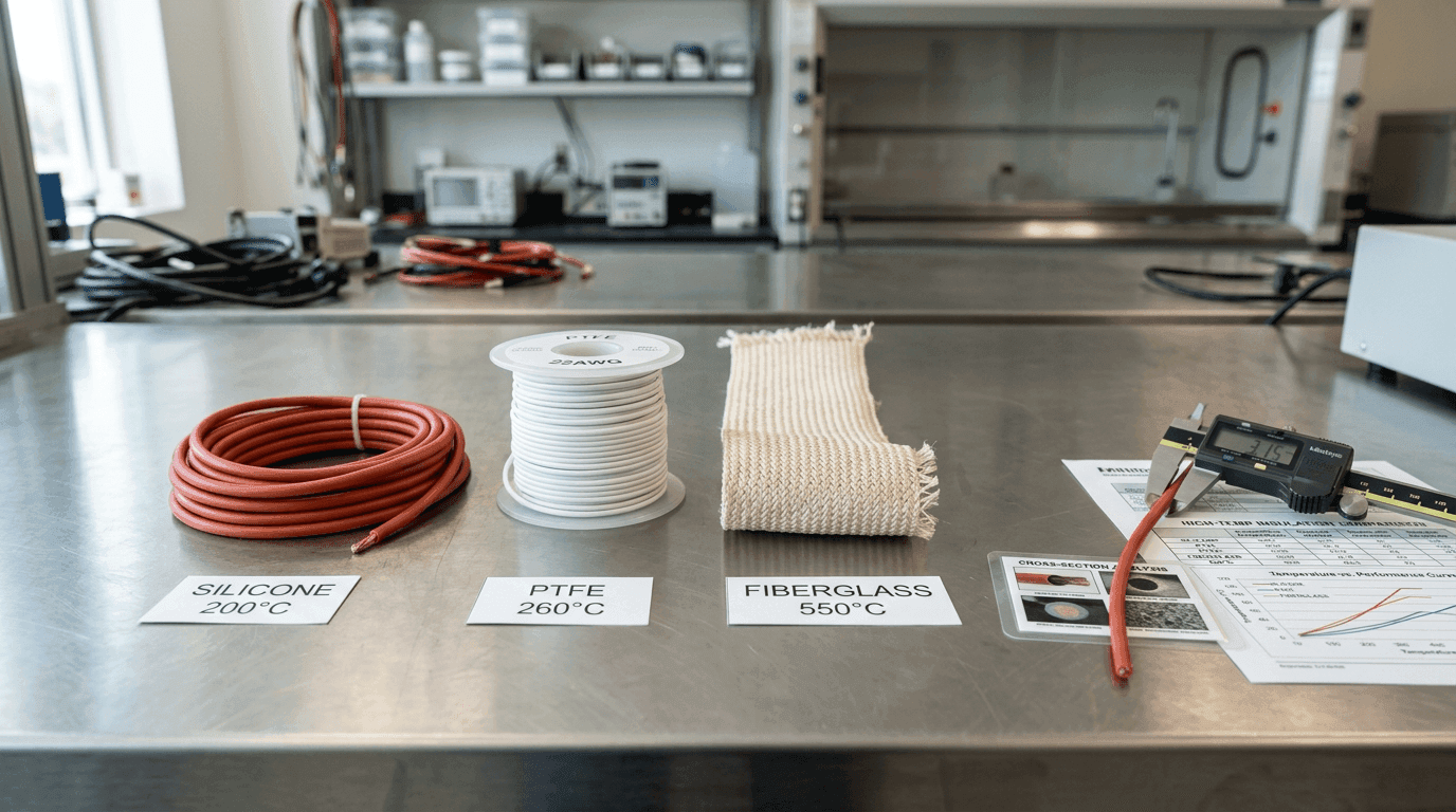
Inner insulation does two things: electrical isolation between the conductor pair, and thermal conduction between the jacket and the compound. The three polymer families that dominate this layer are silicone, fluoropolymer (PTFE and FEP) and fiberglass, and the choice between them is rarely made on insulation life alone. Thermal diffusivity, dielectric strength and chemical compatibility with the surrounding atmosphere all sit in the same selection. The silicone versus PTFE versus fiberglass insulation comparison lays the three property tables side by side and shows which axis is decisive for which application.
Outer jacket
The outer jacket is the cable's only direct interface with the working ambient. It dominates chemical resistance, mechanical durability, smoke-toxicity behaviour and a meaningful share of the unit cost. The jacket also sets the IP rating envelope and the flame-propagation classification, both of which feed directly into the compliance package. Jacket choice is more a specification-sheet decision than a materials-physics one, and it is covered alongside the spec-sheet field-five discussion in the thermal sensor cable specification guide.
Termination metallurgy
The termination is the layer most spec sheets under-document. A metallic conductor pair meets a panel-side terminal, a crimp or a solder joint at each cable end, and the contact metallurgy between the conductor end and the panel hardware sets the long-term contact resistance. On ambient-rated cable that end is usually copper-based (tinned or nickel-plated copper); a high-temperature or resistance-wire construction may bring a nickel-chromium alloy to the terminal. Landed on brass, tinned-copper or stainless, each combination ages differently. Galvanic corrosion at the dissimilar-metal interface is a slow drift mechanism that surfaces after several years of service, not year one. A dedicated engineering note on termination metallurgy, aging and drift covers how the junction corrodes, why the loop drifts at its ends rather than along its length, and how to specify and terminate against it.
Architecture Axis — Thermal Cable Internal Architecture
The same five materials can be stacked in two ways, and the choice between them changes the cable's behaviour in service more than most data sheets admit. Thermal cable internal architecture is the question of how the conductor pair, the thermosensitive compound and the inner insulation relate to each other inside the jacket, and which of the two relationships your route actually needs.
Metal-core architecture
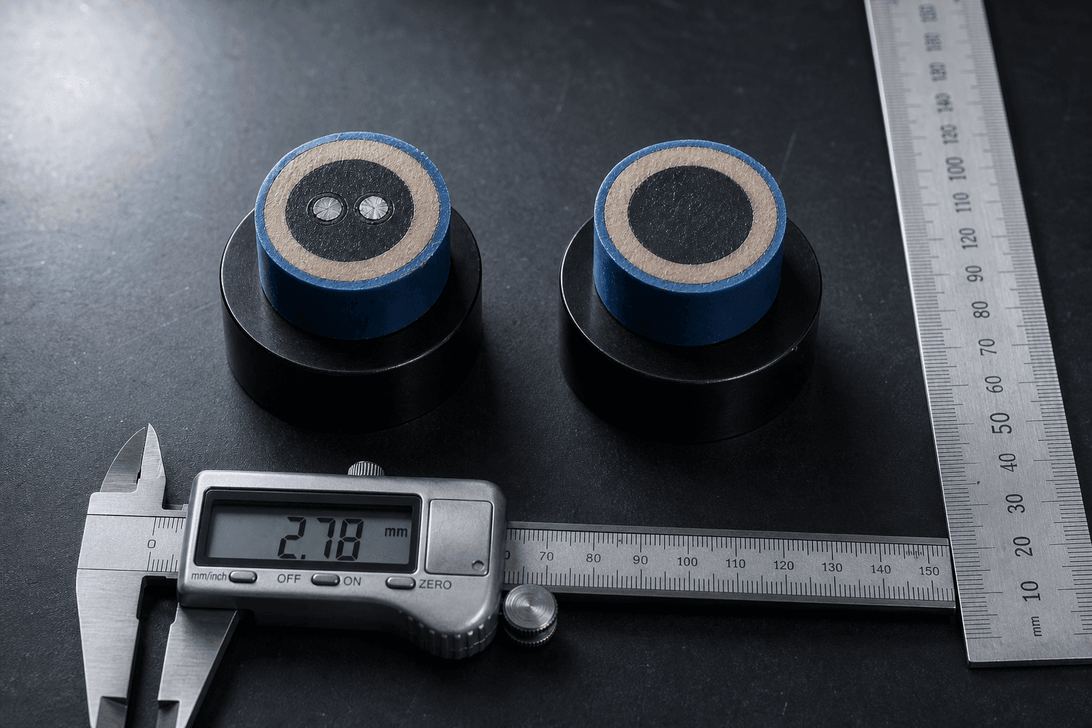
In a metal-core cable, two metallic conductors run continuously along the active length, separated by the thermosensitive compound. Below the activation point the compound is an insulator and the two conductors form an open circuit; at the activation point the compound's resistance collapses and the conductor pair closes through it, presenting a panel-readable short. The metal-core variant is widely used on dry-contact linear heat detection circuits because the activation edge is sharp and the loop reading is clean. It is also the architecture that uses the alloy decision most heavily, because the continuous metal pair carries the entire loop signal.
Non-metal-core architecture
In a non-metal-core cable, no continuous metallic conductor runs through the active section. The thermosensitive compound itself is the resistive path, and the cable behaves as a temperature-dependent resistor whose value falls predictably as the compound passes the activation point. The non-metal-core architecture is mechanically more forgiving (there is no thin metal pair to deform under crush, vibration or sharp bend reversals) and it is simpler to terminate on site because the cable ends behave like the terminals of a single resistor rather than the legs of a pair. Per-metre unit cost typically favours non-metal-core; per-installation cost depends on the panel hardware and the integrator's familiarity.
The trade pattern between the two architectures sits on five engineering dimensions. The table below names the dimensions in the order a procurement engineer usually meets them; nothing in either column makes one architecture universally better, and the choice closes on which dimensions the deployment route actually loads.
| Dimension | Metal-core | Non-metal-core |
|---|---|---|
| Response window | Steep, panel-readable resistance step at the activation point. | Resistance falls with temperature on a smoother slope; activation edge is less abrupt than the metal-core step. |
| Mechanical robustness | Two thin metallic conductors can deform under heavy crush, vibration or sharp bend reversals. | No continuous metallic pair to deform; tolerates crush, vibration and bend cycling better. |
| Termination | Conductor-pair termination at each cable end; accepts standard EOL termination hardware. | Cable ends behave like a single resistor; fewer specialised fittings, simpler on-site termination. |
| Cost band | Higher per-metre unit cost; the conductor alloy decision drives a meaningful share of the bill of materials. | Lower per-metre unit cost; per-installation cost depends on panel hardware and integrator familiarity. |
| Dry-contact panel fit | Reads cleanly on dry-contact LHD circuits that expect a sharp closing edge at activation. | Reads as a temperature-dependent resistor; fit depends on the panel's input topology and the integrator's familiarity. |
Why the cross section matters more than the data sheet line
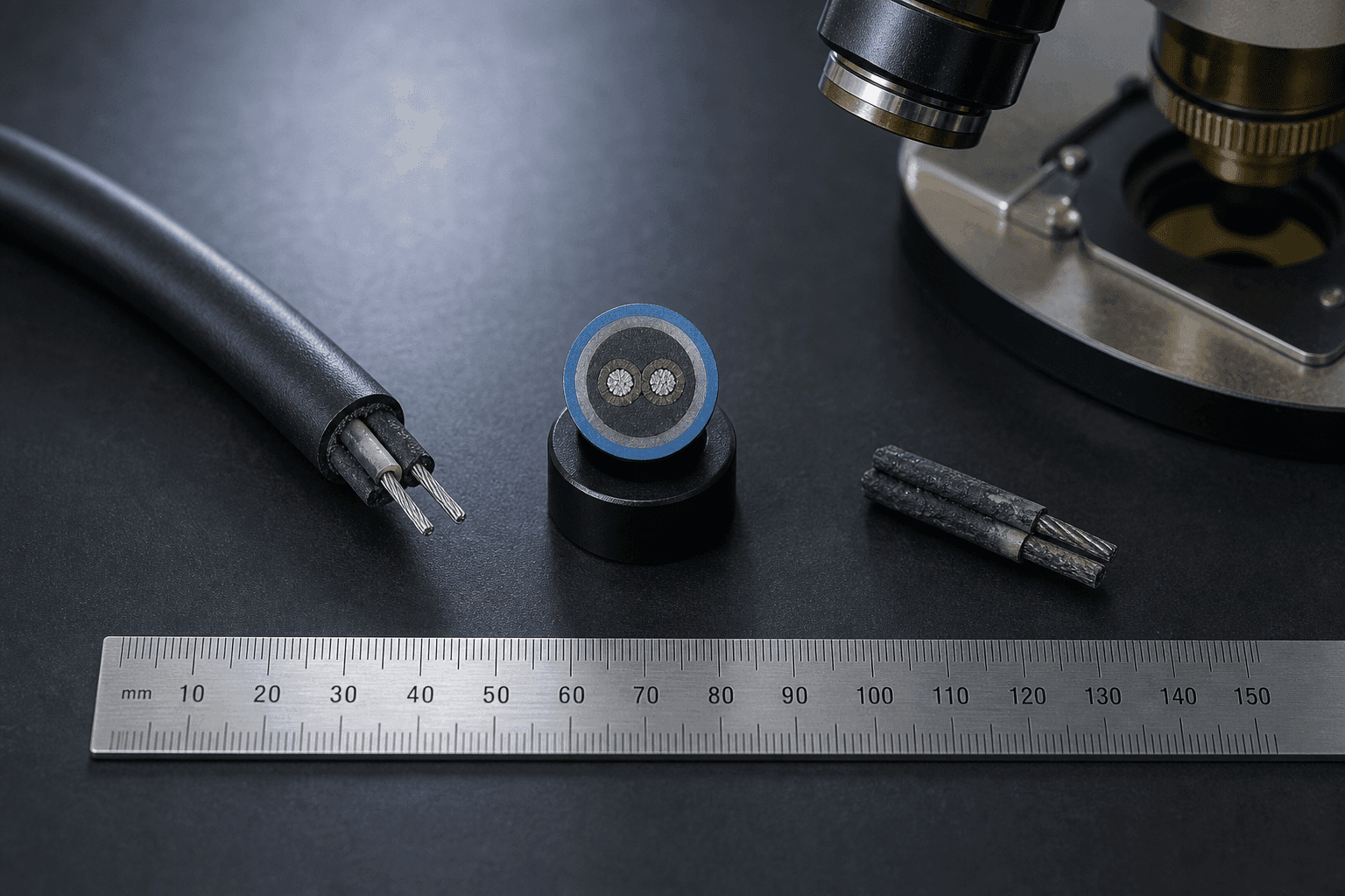
Two cables can read the same on a printed spec (same activation point, same jacket, same diameter, same compliance package) and still be metal-core in one quote and non-metal-core in the next. The substitution is not visible until the cable is sectioned. The architecture choice earns its row on the spec sheet when the route punishes the cable mechanically (heavy vibration, conveyor crush, sharp bends), when the panel needs the sharpest possible activation edge, or when the install crew works under termination time pressure. A dedicated cross-section comparison of metal-core and non-metal-core architectures sits in a separate engineering note; the single-architecture layer-by-layer reference sits in the thermosensitive cable anatomy and trigger physics note.
Time Axis — Thermal Sensor Cable Failure Mechanisms Overview
A thermal sensor cable failure mechanisms overview is essentially a tour of the time axis. None of the four active material layers — conductor alloy, compound, inner insulation and outer jacket — stays still; each ages by a different mechanism on a different time horizon, and the visible failure mode at year five depends on which atmosphere the cable lived in and which duty cycle it was run on. The four headline aging families below cover most of what the route will surface over a ten-year deployment; termination metallurgy is treated separately in the materials axis above. The procurement-side response to these mechanisms is in activation temperature selection: the class and tolerance band a buyer writes on Field 2 should leave room for the drift directions described below, rather than chase year-one accuracy alone.
Oxidation drift
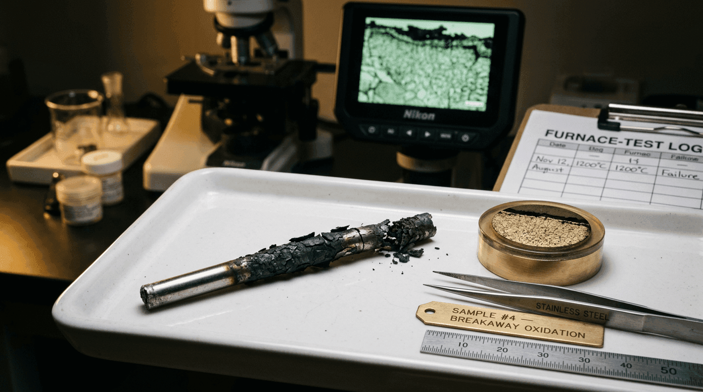
Oxidation is the slow leader on dry indoor and lightly oxidising routes. For Ni80Cr20 conductors, the dominant mode is chromium depletion of the protective oxide layer, which surfaces as a slow upward drift in conductor resistance and a slow downward drift in activation accuracy over years. In sour-gas atmospheres containing H2S or SO2, sulfidation attacks the same chromium reservoir on a horizon of months rather than years and is the early failure mode rather than the late one. In coastal or chloride-laden routes, halogen attack on the jacket polymer is what surfaces first: the conductor reads no drift, but the jacket cracks and the loop fails an IP test before the activation point has moved. The detailed walk-through sits in the rapid-oxidation metallurgy of thermal wire failure note.
Cycling fatigue
Cycling fatigue is the mechanism that shows up on cables routed near PWM heaters, variable-frequency drives, or any thermal source whose envelope sweeps the cable through repeated heat-cool transitions. The thermosensitive compound recovers each cycle but never perfectly; small permanent property changes accumulate, and the activation point drifts after several hundred to several thousand cycles depending on the compound chemistry and the temperature swing amplitude. The dedicated treatment of how that residue accumulates, and how to specify and verify against it, is in the thermal cycling fatigue and compound recovery note; the procurement-side response — derating the cable in cyclic-duty routes — is covered in our cyclic-duty heating-wire derating playbook.
Moisture ingress drift
Moisture ingress is the mechanism that surfaces on outdoor, condensate-prone or wash-down routes whose installed IP rating is lower than the cable's specified IP rating. Moisture entering through a termination cap, a damaged jacket section or an under-rated splice changes the dielectric properties of the inner insulation and slowly shifts the panel's loop reading. In this failure pattern the conductor is not corroding and the compound is not aging — the panel just reads a different baseline. The diagnosis playbook for this is in our field diagnosis of LHD cable short-circuit and false-alarm conditions note, and the selection side — where water actually enters a loop and how to specify the IP that holds — is in moisture ingress and the IP rating re-visited.
Dielectric drift
Dielectric drift is the slowest of the four mechanisms and the hardest to detect, because nothing in the cable looks wrong from the outside. The inner insulation polymer ages at temperature; its permittivity and dielectric strength change gradually, and the activation edge that used to be a sharp step becomes a softer slope. Drift of this kind is what eventually retires a cable that has been in service for ten or fifteen years on a stable route: the cable still activates, just not at the same temperature it activated at on year one. A dedicated note on insulation dielectric behaviour versus temperature covers how these properties move with heat, and separates this permanent aging drift from the reversible temperature swing a hot cable shows day to day.
Response Time — Where Materials, Architecture and Time Intersect
Most engineering questions worth asking about a thermal sensor cable end up at one specific intersection of the three axes: the response time at the activation point. Two cables with the same printed activation point can alarm twenty seconds apart on the same temperature step, and the gap is the combined product of insulation thermal diffusivity, jacket wall thickness, compound chemistry and the architecture's resistance step. On routes where the response window is large (open ceilings, slow-moving warehouse air, atmospheric cable trays under shade), the gap is invisible and the cable simply activates. On routes where the response window is narrow (large-area conveyors, fast-moving extract air, cyclic-duty hot zones), the same gap is the line between a cable that meets its alarm time and one that does not.
The full response-time engineering walk-through sits in our response time engineering for thermosensitive cable note. From this index page, the question is not how response time is engineered but where to go for the answer to a specific response-time question: insulation comparison for material-driven response, architecture comparison for resistance-step-driven response, cycling fatigue note for response degradation over time.
Index — Where to Go Next
This page is an index, not a destination. If you arrived with a specific engineering question, the table below routes the question to the deep-dive note that answers it.
| If the question on your desk is... | The answer sits in... |
|---|---|
| "Should this cable run on NiCr or FeCrAl conductors?" | Ni80Cr20 versus Kanthal A1 conductor decision |
| "What conductor alloy fits a sustained-high-temperature route?" | Conductor alloy framework for NiCr, FeCrAl and superalloy |
| "How does the cable actually trigger? What is inside one?" | Thermosensitive cable anatomy and trigger physics |
| "Which insulation polymer should this route use?" | Silicone, PTFE and fiberglass insulation comparison |
| "Why does a thermal wire burn out early?" | Rapid-oxidation metallurgy of thermal wire failure |
| "Why do two same-spec cables alarm at different times?" | Response time engineering for thermosensitive cable |
| "How does the cable behave near a PWM heater?" | Cyclic-duty heating-wire derating playbook |
| "How do I write a spec sheet that survives a three-party review?" | Thermal sensor cable specification guide |
A printed activation point on a cable jacket is one line on a data sheet. Thermal sensor cable engineering is the discipline of designing five layers, choosing one architecture and accounting for four failure mechanisms so that ten years later the activation reading still falls inside the specified tolerance band, assuming the route conditions match the original specification.
FAQ — Thermal Sensor Cable Engineering
Why do two thermal sensor cables with the same printed activation temperature behave differently?
The printed activation temperature is one line on a data sheet; what the cable actually does in service is the sum of four engineering decisions underneath it. The conductor alloy sets temperature-coefficient linearity and how the loop resistance reads through the working ambient. The thermosensitive compound sets the slope of the resistance collapse at the activation point. The insulation sets thermal diffusivity from jacket surface to compound. The cable architecture — metal-core or non-metal-core — sets how steep the resistance change is and how clean the panel signal looks. Add ten years of oxidation drift, cycling fatigue and moisture ingress on top of all four, and two cables stamped 105 °C can drift apart by 20 K or alarm 20 seconds apart on the same circuit. Thermal sensor cable engineering is the discipline of engineering each of those decisions so the activation reading in year ten still falls inside the specified tolerance band when the route conditions match the original specification.
What is the difference between metal-core and non-metal-core thermal sensor cable architecture?
Metal-core architecture pairs two metallic conductors — typically Ni80Cr20 or nickel-plated copper — separated by a thermosensitive compound; the conductors form a closing short across the compound at the activation point. Non-metal-core architecture relies on the thermosensitive compound itself as the resistive path with no continuous metallic conductor through the active section. The two architectures trade three things differently: response sharpness (metal-core gives a steeper resistance step, useful when a panel needs a clean activation edge), mechanical robustness (non-metal-core tolerates crush and vibration better because there is no thin metallic pair to deform), and termination simplicity (non-metal-core is easier to terminate on site with fewer specialised fittings). Per-metre unit cost typically favours non-metal-core; per-installation cost depends on the panel and the route. A spec sheet that names the architecture explicitly in the geometry field protects the project against the supplier substituting one for the other on cost grounds during a long-running RFQ.
Which failure mechanism shows up first on long-deployed thermal sensor cable?
The first failure mechanism to surface depends on the atmosphere the cable lives in, not on cable quality alone. In dry, inert or mildly oxidising indoor environments, the slow leader is conductor oxidation — for Ni80Cr20 this typically means chromium depletion of the protective oxide layer over a horizon of years. In sour-gas environments containing H2S or SO2, sulfidation attacks the same chromium layer in months rather than years and is the early failure mode. In coastal or chloride-laden routes, halogen attack on the jacket polymer is the visible signal first, before the conductor reads any drift. In cyclic-duty routes near PWM heaters or frequency drives, cycling fatigue of the thermosensitive compound shows up before any atmosphere mechanism has had time to act. Each path links to a different engineering response — alloy change, jacket change, route re-engineering or compound reformulation — which is why the audit before the spec sheet matters more than the spec sheet itself.
Why does insulation material affect activation time on a thermal sensor cable?
Insulation is not a passive wall; it is the thermal-conduction path between the working ambient and the thermosensitive compound. Each polymer family has its own thermal diffusivity, density and specific heat, and the combination of those three sets the lag between a temperature step at the jacket surface and the same step reaching the active sensing region. Silicone, fluoropolymer (PTFE / FEP) and fiberglass behave differently across the activation range: silicone runs warmer and conducts heat faster than PTFE at the same wall thickness; PTFE adds insulation life but slows the response edge; fiberglass tolerates extreme ambients and conducts heat well, but its mechanical envelope rules it out for routes that need flex life. Two cables with the same printed activation point and the same conductor pair can alarm twenty seconds apart simply because the jacket wall and the insulation polymer move the heat differently. On routes where seconds matter — large-area open ceilings, fast-moving conveyor galleries, cyclic-duty hot zones — the insulation choice is the engineering decision, not a downstream brochure line.