A thermosensitive cable looks like a length of insulated wire. The physics hiding under the jacket is anything but ordinary. This note walks through the cable's anatomy the same way we walk a new engineer through it on their first day in the factory — conductor, compound, jacket, trigger — and explains why each choice has to be deliberate.
The Four-Layer Architecture
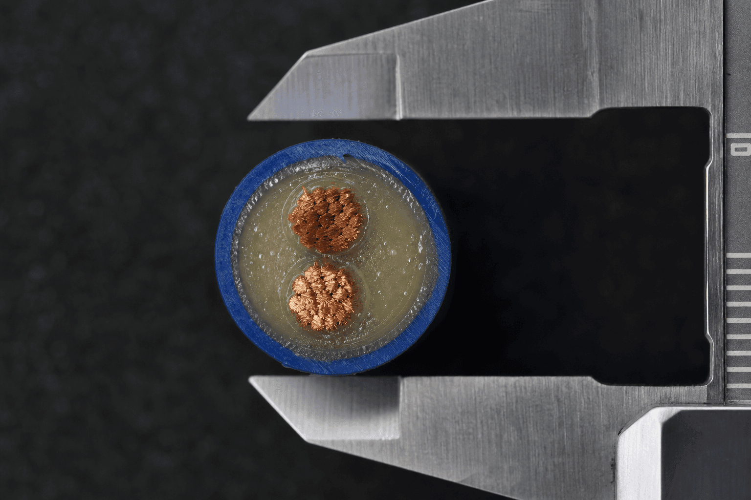
Every thermosensitive cable we build is a stack of four functional layers, concentric around the cable axis:
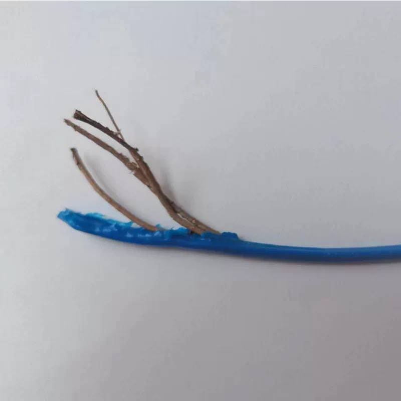
- Conductors. Two (sometimes more) drawn metal strands twisted on a calibrated lay-length. Typically tinned copper or nickel-copper alloy to hold contact resistance stable over years of sub-activation heat exposure.
- Thermosensitive compound. The functional layer. A proprietary polymer formulation that remains a stable dielectric below the rated activation point and collapses — predictably, repeatably, at a calibrated temperature — above it.
- Structural insulation. A thin mechanical buffer that keeps the cable geometry stable in service but does not carry the activation behaviour itself.
- Outer jacket. The colored protective skin (blue for LHD, red for TS, or customer-matched). Carries the mechanical, chemical, UV and waterproof duties.
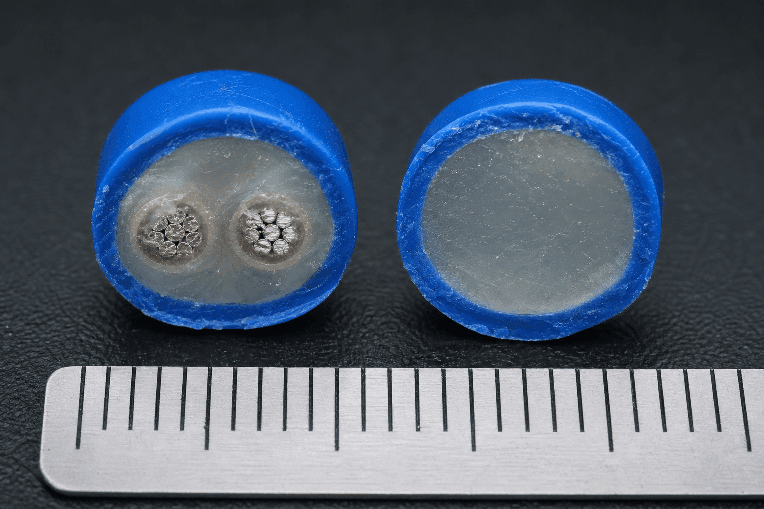
Two Core Architectures — When to Specify Which
Metal-Conductor Core (the workhorse)
Two parallel or twisted metal conductors, separated by the thermosensitive compound. Under normal conditions, the compound is a stable dielectric — the conductors cannot see each other. At the activation point, the compound collapses and the conductors short. The panel sees a clean dry-contact event.
Pick this architecture for:
- LHD loops on addressable or conventional fire panels
- Appliance over-temperature cut-off circuits
- Any detection topology where the downstream device expects a short-on-activation signal
Non-Metal Core (specialised)
No metal conductor along the central axis. The detection topology relies on the combustion-propagation behaviour of the thermosensitive compound itself — usually in combination with a suitable external monitoring circuit. Less common, but the right answer when metal conductors would introduce an electromagnetic or galvanic problem in the detection zone.
Trigger Physics — Two Events, One Cable
Trigger 1: Thermal-Threshold Collapse
The thermosensitive compound is engineered to hold dielectric strength steady from -40°C up to just below its activation point. Above that point, the compound undergoes a rapid softening (for some formulations) or decomposition (for others) — the molecular network loses its load-bearing structure. The two conductors close the gap and the panel sees a short. Response time is typically a few seconds.
Trigger 2: Flame-Contact Ignition
A direct flame is a different physical event. The jacket and compound ignite, and the burn front propagates along the cable at a calibrated 3–10 seconds per meter. In practical terms, that means any point of the cable reached by flame will alarm within seconds, regardless of ambient temperature elsewhere on the run.
The dual-trigger design is what makes thermosensitive cable trustworthy for fire detection. Relying on only the temperature mechanism misses flash-flame events; relying only on flame contact misses slow-heating smouldering fires. A real cable does both.
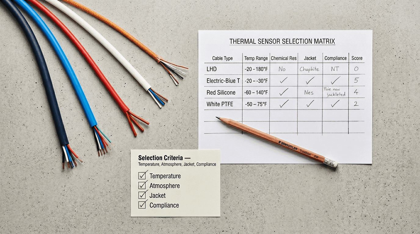
Material Choices That Actually Change Performance
If the conductor, compound or jacket is off, the whole cable is off. These are the choices that show up in service:
- Conductor alloy. Pure copper is the default; tinning resists oxidation in humid service; nickel-copper is the right answer in salt-spray or chemical-plant environments.
- Compound formulation. Activation point is tuned by polymer chemistry and filler ratio, not by changing "how thick" anything is. The nominal number matters; the batch-to-batch spread matters more.
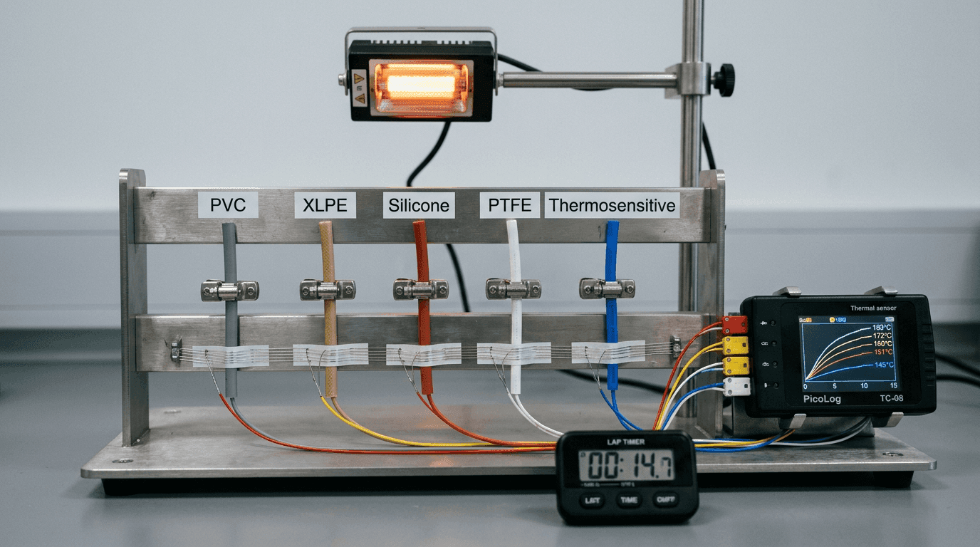
- Jacket polymer. PVC for indoor low-cost runs, LSZH where smoke-toxicity codes forbid PVC, silicone for high-ambient motor applications, fluoropolymer for chemical environments.
- Wall thickness. Thicker jacket = slower response. Response time can be engineered by wall thickness alone — we regularly do this for customers with ambient-rejection requirements. The quantitative model behind that choice (diffusivity, the L² scaling and a property table for each insulation family) is in engineering the response time of a thermosensitive cable.
How QC Verifies This Stack
The four-layer architecture only behaves the way the diagram says if every layer holds its tolerance. That is what our outgoing inspection actually pins down — jacket geometry, conductor lay-length, compound activation point, response-time uniformity along the spool, and a handful more. The full nine-parameter QC pass sits in its own note, but the short summary is that every shipment leaves with a per-batch report keyed to the lot number printed on the jacket. If a number on that report is missing, the cable did not pass.
Closing Thought
Once you understand the four-layer anatomy and the two trigger mechanisms, specifying a thermosensitive cable becomes a matter of matching layer choices to your application constraints — not picking a catalog part number and hoping. The walk-through above sits inside a single architecture — the metal-conductor variant — and the buyer-side comparison between that variant and the non-metal-core alternative, with five engineering axes and five deployment scenarios, is in our companion cross-section comparison of metal-core and non-metal-core architectures. The two cut-off architectures the cable then drops into — one-shot fusible vs resettable PTC — are unpacked in one-shot or resettable thermal cutoff cable: the spec decision; the OEM integration patterns that exploit this anatomy sit in thermosensitive cable as the last line of appliance safety. That is the level of conversation our engineering desk prefers.
If you would like a formulation walk-through against your specific application, message engineering — we will share a data pack and an evaluation sample (subject to sample availability and project review).
FAQ — Thermosensitive Cable Anatomy
What are the four layers inside a thermosensitive cable?
Every thermosensitive cable is built as four concentric functional layers around the cable axis: (1) two or more drawn metal conductors, typically tinned copper or nickel-copper, twisted on a calibrated lay-length; (2) a thermosensitive compound — a proprietary polymer formulation that holds dielectric strength below the rated activation point and collapses predictably above it; (3) a thin structural insulation layer that keeps cable geometry stable in service; and (4) the outer jacket, which carries mechanical, chemical, UV and waterproof duties.
How does a thermosensitive cable actually trigger an alarm?
A thermosensitive cable triggers on two independent physical events. The first is a thermal-threshold collapse: above the rated activation point, the compound's molecular network loses load-bearing structure, the two conductors close the gap, and the panel sees a clean dry-contact short. The second is flame-contact ignition: a direct flame ignites the jacket and compound, propagating a burn front along the cable at a calibrated 3–10 seconds per metre. Either event drives the alarm.
What is the difference between metal-conductor and non-metal-core thermosensitive cable?
The metal-conductor architecture (the workhorse) places two parallel or twisted metal conductors separated by the thermosensitive compound; on activation, the compound collapses and the conductors short — this is the default for LHD loops, appliance over-temperature cut-off circuits, and any panel expecting a short-on-activation signal. The non-metal core has no metal conductor along the central axis and relies on combustion-propagation behaviour of the compound itself with an external monitoring circuit. It is specialised — used only where metal conductors would introduce electromagnetic or galvanic problems in the detection zone.
Can the response time of a thermosensitive cable be tuned?
Yes. Response time is engineered primarily through jacket wall thickness and compound formulation. A thicker jacket slows the heat path to the compound and lengthens response; a thinner one accelerates it. Conductor geometry, compound filler ratio and lay-length are secondary levers. Two cables with the same activation temperature can alarm 20 seconds apart depending on these choices — which is why specification has to match the application's thermal-rejection requirements rather than copy a generic datasheet.