A thermal sensor cable installed beside a cyclic-duty heater has a harder job than the same cable in a quiet cable tray. PWM drivers, solid-state relays and short-cycle process sequencers create a moving heat envelope: hot enough to demand independent protection, but not hot enough on every cycle to justify an alarm. If the cable is too close, it nuisance-trips on every start-up. If it is too far away, it misses the local hot spot that destroys the insulation, product or enclosure.
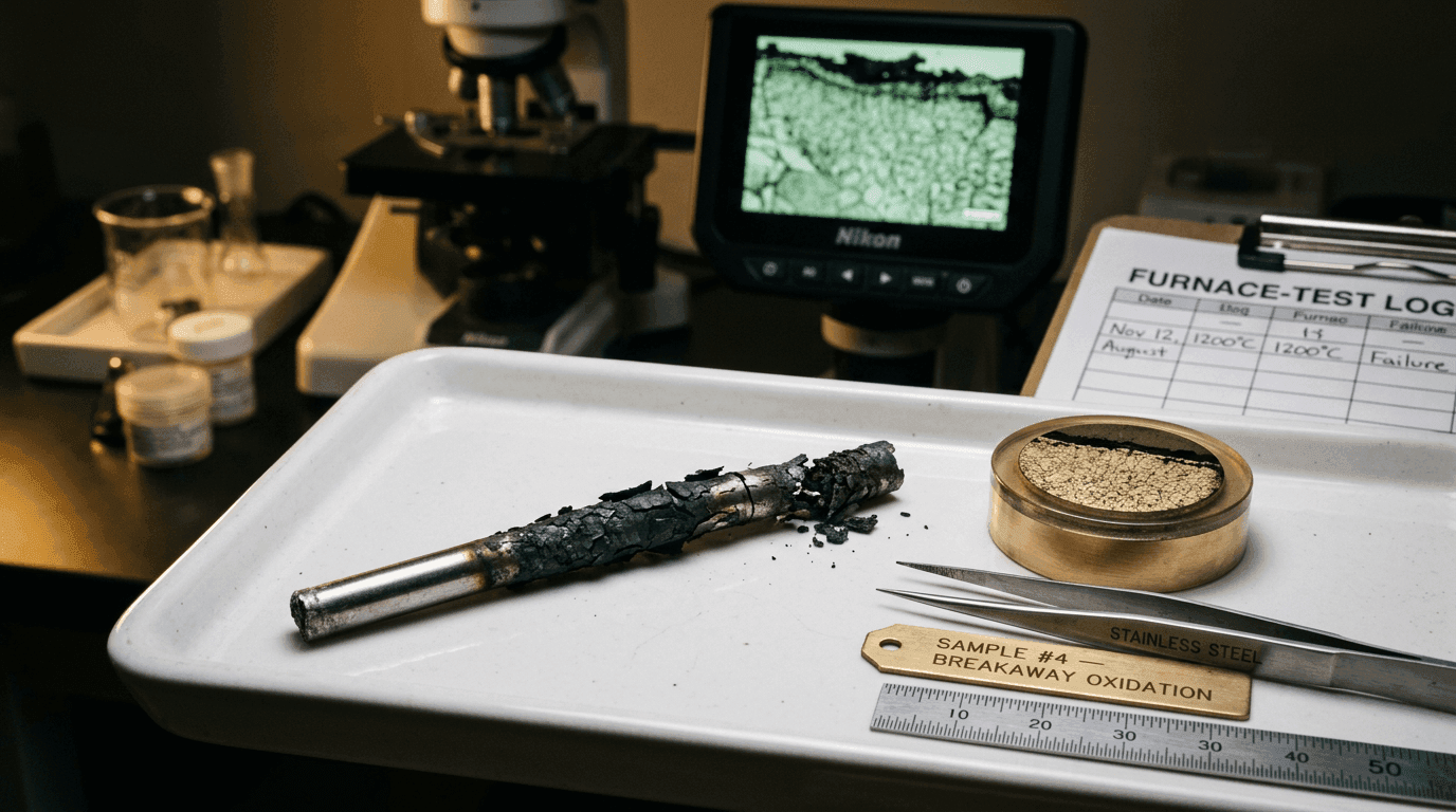
This note is written for engineers specifying thermal sensor cable near cyclic-duty heaters: drying tunnels, laminators, reflow fixtures, battery thermal rigs, motor test stands, appliance hot zones and short-cycle industrial heaters. We use the heater's pulse profile to set the cable route, jacket material, activation point and alarm margin — so the cable protects the asset without becoming the source of false alarms. The five upstream specification mistakes that turn this from a placement problem into a recall problem are catalogued in five thermal sensor cable specification mistakes that shorten service life; the long-term metallurgical failure pattern under repeated thermal cycling is the subject of why thermal wire burns out early — the metallurgy of rapid oxidation, and how the repeated cycling slowly drifts the sensor cable's own activation point over its service life is covered in thermal cycling fatigue and activation drift.
Three Risk Axes, Not One
A steady hot surface is simple to monitor: choose a cable rated above normal ambient and below the damage threshold. Cyclic duty adds two more axes on top of temperature.
- Normal pulse heat. The cable route may see repeated benign temperature peaks that must not trigger an alarm.
- Abnormal local hot spots. A failed relay, blocked airflow, fallen insulation pad or loose heater support can move the hot zone onto the cable path.
- Mechanical and chemical exposure. The same zone often carries vibration, oil mist, condensate and abrasion that decide jacket life long before the compound reaches activation.
A thermal-cable specification around cyclic-duty heaters has to touch all three axes or it under-performs. Choosing only the activation temperature while ignoring placement and jacket chemistry is the common route to nuisance alarms or missed faults.
Specify the cable to the heat envelope it actually sees, not to the heater nameplate — the cable lives a few centimetres away and lives a different thermal life.
Step 1 — Profile the Heat at the Cable Route
Tape a fine-wire thermocouple to the cable's intended jacket position — not to the heater element — and log one complete duty cycle at 2 Hz or faster, with the heater running its normal control loop and the equipment in worst-case ambient. The cable does not need the element's peak temperature; it needs four numbers measured at its own location:
- Cable peak (T_cable_peak) — hottest temperature the jacket sees during a normal heater cycle, including overshoot at start-up.
- Cable valley (T_cable_valley) — coolest temperature reached before the next heater pulse re-energises.
- Cycle period (τ) — the heater's full pulse-to-pulse repeat time, in seconds.
- Cable rise rate (dT/dt) — the average K/s slope when the jacket is heating up, which decides how fast the activation compound responds.
These four numbers tell you whether the cable is exposed to a benign dithering envelope or a real cyclic load that will degrade the jacket. If you can only log one of them, log T_cable_peak: every alarm-margin and jacket decision is built on top of it. We ask every customer for these four values before recommending a placement and activation point.
Step 2 — Classify the Cable Duty Class
| Cable Duty Class | Cycle Period τ | Cable Swing (peak − valley) | Typical Heater Source | Spec Tier |
|---|---|---|---|---|
| Dithering PWM | < 2 s | < 5 K | SSR-driven trim heaters, low-mass elements | Light (≈ steady) |
| Tight PID | 2 – 20 s | 5 – 15 K | Drying tunnels, lamination, reflow profiles | Tier 1 |
| Process cycling | 20 – 120 s | 15 – 40 K | Battery thermal rigs, motor test stands, oven re-heat | Tier 2 |
| Deep on/off | > 120 s | > 40 K | Appliance hot zones, batch dryers, intermittent process heaters | Tier 3 |
The tier drives the rest of the cable specification. A Tier 1 cable position can run a standard PVC- or LSZH-jacketed thermosensitive cable with a 20–25 K activation margin. A Tier 3 position will need a higher-temperature jacket, a higher activation point, or a mechanical shield between cable and heater — sometimes all three. Clipping a stock 68 °C cable directly onto a Tier 3 surface is the single fastest way to generate nuisance alarms.
Step 3 — Translate the Profile into Cable Placement
Standoff axis — distance and orientation. Move the cable off the radiant peak of the element. Where the cable must travel close to a heater, run it on the cooler side (downstream of the protected airflow, behind a sheet-metal shield, or on the underside of a horizontal support) so it sees conducted heat from the hazard you want to detect, not radiant heat from the normal element. A typical rule of thumb: every doubling of standoff cuts the cable peak by 30–40% in still air. Confirm with a thermocouple on Step 1, do not estimate from a CAD drawing.
Activation-margin axis — measured number, not catalog number. Set the activation point at T_cable_peak + 20 K as a minimum, or T_cable_peak + 30 K for Tier 2/3 duty. Stock activation points (68 °C, 88 °C, 105 °C, 138 °C) are coarse — pick the closest catalog point that meets the margin and round up, never down. The margin is what separates a real over-temperature from a normal hot pulse, and it is also what protects you from drift in the heater's PID tuning over the equipment's life.
Jacket axis — chemistry before colour. The cable jacket lives in the same air the heater bracket lives in: oil mist from gearboxes, condensate from off-cycle humidity, solvent vapour from adjacent processes, abrasion from cable trays and panel doors. A silicone jacket survives high ambient and flexes well; a fluoropolymer jacket resists chemicals and oils; LSZH covers smoke-toxicity codes; PVC is acceptable only well away from radiant heat. Pick the jacket from the route audit, then verify the activation compound's substrate compatibility before placing the order.
Alarm-Margin Fixes That Do Not Touch the Heater
Before re-specifying the cable upward, check whether the heat envelope at the cable position can be reshaped. Four interventions we deploy regularly — none of which require changing the heater itself:
- Add a thin radiant shield. A 0.5 mm sheet-metal or ceramic-fibre baffle between cable and element typically drops T_cable_peak by 15–30 K with no airflow penalty. The cable still sees a fault-driven hot zone (because conduction through the bracket changes), but loses the radiant pulse.
- Re-route around the radiant fan. Move the cable off the heater's line-of-sight by 100–150 mm, even if it stays at the same overall standoff distance. Radiant heat falls quickly with angle; conducted-fault heat does not.
- Increase thermal coupling to the protected surface. Clipping the cable tightly to the equipment skin or panel back-plate gives it a thermal sink that cancels brief radiant pulses while still responding to a real hot-spot fault. This is the inverse of "free air" routing — and usually preferred near cyclic heaters.
- Use a higher activation point with a lower-mass jacket. A thinner jacket responds faster, so the same response time can be achieved with more headroom on the activation point. In our deployments it is the most reliable swap for nuisance-alarm sites where the trip is correct but late. Why wall thickness dominates response time is unpacked quantitatively in engineering the response time of a thermosensitive cable.
Jacket and Activation Choices for Cable Beside Cyclic Heat
Three jacket families cover almost every cable installation near a cyclic-duty heater. Choose the family by route chemistry and ambient ceiling, then pick the activation point from the cable peak you measured.
| Cable Route | Jacket | Activation Range | Notes |
|---|---|---|---|
| Indoor cable tray, dry plant | PVC or LSZH | 68–88 °C | Smoke-toxicity code may force LSZH in tunnels and atria |
| Motor or heater-adjacent route | Silicone | 88–138 °C | Flex tolerant, high ambient — pair with abrasion sleeve where it touches metal |
| Oil mist, solvent, food-process | PTFE or FEP | 105–138 °C | Stiff but chemical-resistant — confirm bend radius at panel entry |
| Battery rig, lab fixture, OEM enclosure | Fiberglass-reinforced silicone | 88–105 °C | Low-mass response, suits short cycles and tight cabinets |
Behind every selection is the same rule: the jacket's continuous service ceiling must sit at least one tier above T_cable_peak, and the activation compound has to clear the peak by the margin in Step 3. For a deeper jacket comparison, see our silicone, PTFE and fiberglass selection note.
Expected Reliability Gain
The table below is calibrated against site reports from reflow ovens, plastic-welding stations, battery thermal rigs and laser-diode chillers where we replaced an off-the-shelf cable installation with a placement-and-margin specification. The "before" cases were most often nuisance-alarm complaints — the cable was triggering on normal cycles or, less often, missing real faults. Numbers are independent, not additive.
| Intervention | Typical Effect |
|---|---|
| Move cable off radiant line-of-sight by 100–150 mm | T_cable_peak −15 to −25 K |
| Add 0.5 mm radiant shield between cable and element | T_cable_peak −15 to −30 K |
| Increase activation point by one catalog step (e.g. 88 → 105 °C) | Nuisance alarm rate down 50–80%, fault detection unchanged |
| Switch from PVC to silicone jacket near hot bracket | Jacket service life 2–4× longer; no embrittlement after 12 months |
| Tight clip to protected skin (vs free-air routing) | Cable swing per cycle cut by 40–60%; faster real-fault response |
| Independent panel input (not tapped off heater resistance) | Removes the dependency loop that hides PID-drift faults entirely |
Commissioning Checklist for Cable-Adjacent Heaters
- Measured T_cable_peak, T_cable_valley, τ and rise rate logged on the cable jacket in worst-case ambient — not nameplate numbers and not heater-element data.
- Cable duty tier classified (Light / Tier 1 / Tier 2 / Tier 3) and written onto the cable specification.
- Standoff and orientation documented on the installation drawing — distance from element, side relative to airflow, presence of radiant shield.
- Activation point chosen as T_cable_peak + 20 K minimum (Tier 1) or +30 K (Tier 2/3), and rounded up to the nearest catalog point.
- Jacket family selected against route chemistry (silicone / fluoropolymer / LSZH / PVC), with abrasion or chemical sleeve where the cable touches metal or sees mist.
- Cable routed into an independent panel input — fire-alarm relay, OEM cut-off contactor or PLC digital input — not derived from heater resistance, current or controller status.
- Commissioning soak: run the heater through a worst-case duty cycle with the cable in place, log the cable peak, and confirm at least 20 K of headroom against the activation point before signing off the loop.
A Concrete Example — Sensor Cable on a Laser Diode Chiller
An optics integrator was getting nuisance over-temperature trips on a laser-diode chiller about every 30–40 production hours. The chiller's internal trim heater cycled between 30% and 95% duty every 14 seconds to hold the diode-mount temperature within ±0.1 K. The original install used a 68 °C activation, PVC-jacketed thermosensitive loop clipped directly to the heater bracket. T_cable_peak measured 71 °C during a normal cycle, T_cable_valley 58 °C — the cable was being triggered every time a long process pulse came through, even though no fault was present.
We moved the cable 120 mm off the radiant line-of-sight to the underside of the chiller's panel back-plate, swapped the jacket to silicone (continuous service to 200 °C, ambient ceiling far above the new route), and stepped the activation point to 88 °C — a 23 K margin above the new measured peak of 65 °C. Same chassis, same control loop, no firmware change. Nuisance trips went from 3–4 per week to zero across two months of production. The integrator added the same placement spec to two follow-up chiller variants and standardised it across the platform.
Where Aetherm Fits
If you need a thermal sensor cable beside a PWM heater, short-cycle element or pulsed hot zone, send us the pulse-profile log, cable route sketch, highest normal ambient and fault you want to catch. Our engineering desk returns a cable recommendation — LHD Series for fire-panel loops or TS Series for in-equipment cut-off — with jacket material, standoff distance, activation point and commissioning checks. Brief the engineering desk and we will size the alarm path around the heat envelope, not around a catalog cable.
FAQ — Cable Near Cyclic-Duty Heaters
Where should thermal sensor cable be placed near a cyclic-duty heater?
Place the cable where it sees the same thermal event that threatens the asset, but not the normal radiant peak of the heater. In practice that means offset from the element, tied to the protected surface or cable tray, and shielded from direct flame or coil contact unless flame-contact activation is part of the design. The correct standoff is set by the pulse profile: peak temperature, valley temperature, cycle period and cool-down slope.
How much alarm margin does a sensor cable need around PWM heaters?
Set the activation point above the highest legitimate sensor-cable temperature during normal PWM operation, including worst-case ambient, enclosure soak and start-up overshoot. A practical minimum is 20–30 °C above the measured normal cable temperature, or a tighter engineered margin when the cable is thermally isolated from the element. Do not use heater-wire peak temperature as the cable setpoint; measure the cable route.
Which jacket material is the most suitable choice near cyclic-duty heaters?
Use silicone when the cable sits near hot metal or motor windings and needs flexibility at elevated ambient. Use fluoropolymer when oil mist, solvent vapour or chemical condensate is present. Use LSZH where smoke-toxicity codes govern the protected space. PVC is acceptable only when the cable route stays below its ambient rating and is physically separated from radiant heat.
Should thermal sensor cable rely on heater resistance drift for alarm logic?
No. Heater resistance drift is a poor safety signal because the same cycling that causes a hazard also changes the resistance baseline. A thermosensitive cable should provide an independent, binary over-temperature or flame-contact path into the panel, relay or cut-off circuit. That independence is the point of adding cable monitoring beside a PWM or short-cycle heater.
Is external thermal monitoring worth adding to a cyclic-duty heater?
Yes for unattended or product-carrying systems — reflow, lamination, extrusion, drying tunnels, battery thermal fixtures, laser diode blocks and appliance test rigs. A thin, low-mass thermosensitive cable routed beside the hazard gives an independent alarm path that does not depend on firmware or heater resistance drift. The cost is usually lower than one unplanned shutdown.