Pick two thermosensitive cables with the same 105 °C activation point. Drop them into the same ramp oven. One alarms in eight seconds, the other in twenty-eight. The chemistry is identical — the difference is entirely in the insulation. Jacket material, wall thickness and compound kinetics set the thermal sensor cable response time you see in the alarm log.
1. What Response Time Actually Measures
Response time (tr) is the interval between a step change in outside temperature and the moment the sensing element reaches its activation threshold — typically 68, 88, 105, 138, 170 or 185 °C. The activation classes themselves are defined by the line-type LHD standards (UL 521, EN 54-22 for resettable variants, EN 54-28 for non-resettable). Response time is not activation temperature (the set-point itself), not alarm latency (which adds panel processing), and not burn speed (3–10 s/m along an already-ignited cable). It is pure heat transport through the insulation stack.
2. The One-Equation Model
Model the cable as a cylindrical lumped-thermal-mass system and response time collapses to:
tr ≈ (ρ · c · L²) / k
ρ = density (kg/m³), c = specific heat (J/kg·K), L = wall thickness (m), k = thermal conductivity (W/m·K).
The combined metric you design against is thermal diffusivity α = k / (ρ·c). High α, thin L — that is the fast-cable recipe. And because L enters squared, wall thickness is the single most powerful lever on the list.
3. Insulation Property Card
Representative values for production-grade compounds — for any specific SKU, the published datasheet should be treated as the authoritative source.
| Material | k (W/m·K) | ρ (kg/m³) | c (J/kg·K) | Max Continuous T (°C) | Relative Response |
|---|---|---|---|---|---|
| Thermosensitive compound (proprietary) | 0.20–0.30 | 1350–1450 | 1200–1500 | 90 (designed to fail above set-point) | Fastest at set-point |
| FEP (fluorinated ethylene propylene) | 0.20–0.25 | 2140–2170 | 1170 | 200 | Fast |
| PFA | 0.19–0.25 | 2140–2170 | 1050 | 260 | Fast |
| PTFE | 0.23–0.27 | 2150–2200 | 1000 | 260 | Fast |
| Silicone rubber | 0.20–0.30 | 1100–1250 | 1300–1500 | 180–200 | Medium |
| XLPE (cross-linked PE) | 0.28–0.46 | 920–950 | 2300 | 90 (125 short-term) | Medium |
| PVC | 0.16–0.21 | 1300–1450 | 900–1000 | 70–105 | Slow–Medium |
| EPDM / Neoprene | 0.20–0.25 | 1100–1400 | 1800–2000 | 120–150 | Slow |
| Mineral insulation (MgO) | 2.0–3.5 | 3580 | 935 | 800+ | Very fast (high k) but high mass |
4. How Each Family Behaves
Thermosensitive compounds are not classical insulation — they are engineered to fail on cue. At the rated set-point the compound collapses sharply and the two conductors close the loop, routinely delivering under 10 s/m at or above activation. For LHD duty, this is the winning chemistry.
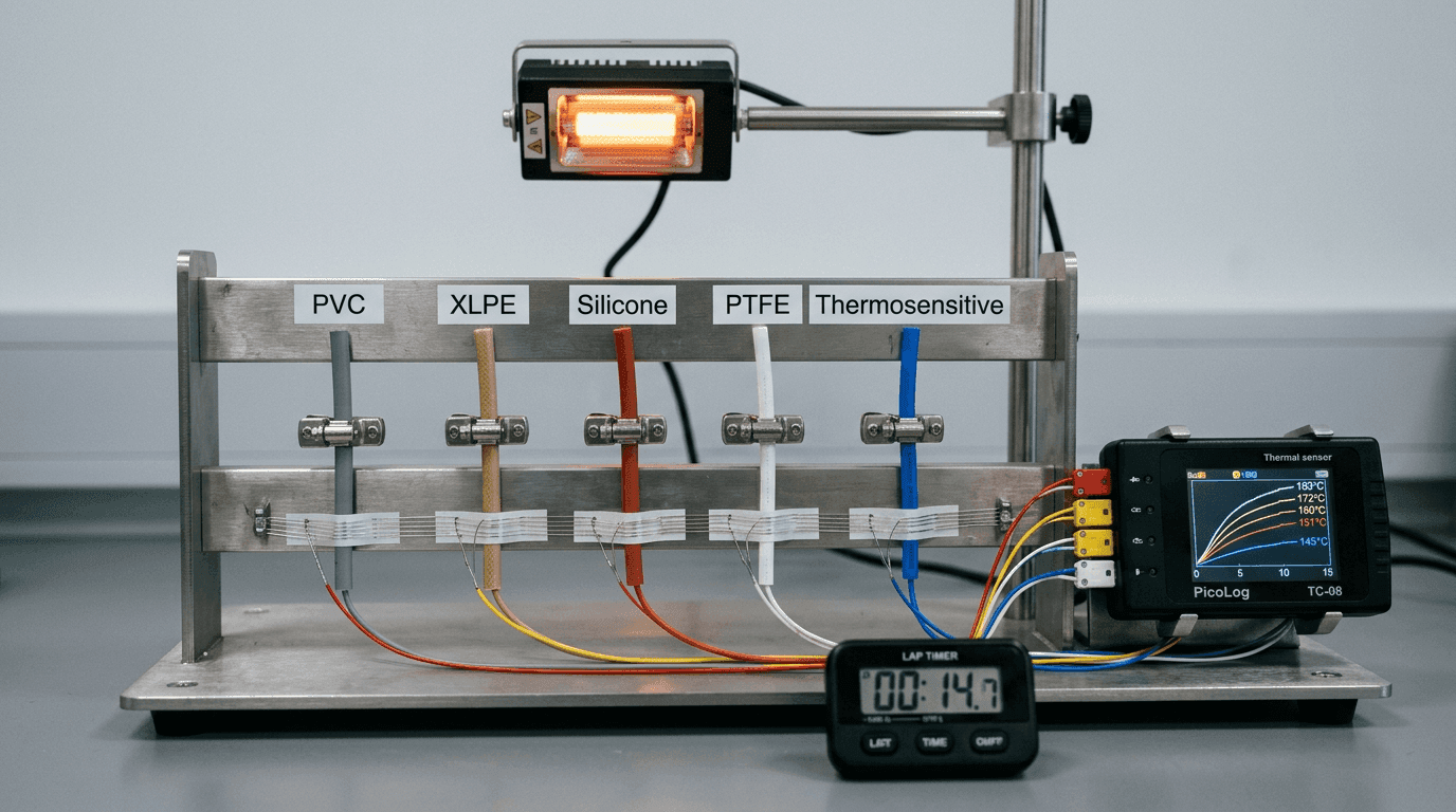
Fluoropolymers (FEP, PFA, PTFE) extrude to 0.10–0.25 mm and hold 200–260 °C continuously. Moderate conductivity plus a thin wall gives the short diffusion path that makes a fluoropolymer thermal sensor cable the default choice near heaters, motors and industrial ovens.
Silicone handles 200 °C and flexes repeatedly, but typical walls are 0.4–0.8 mm — slower response. Right when flex and flame-retardance beat raw speed. XLPE has the highest polymer conductivity in this comparison (~0.46 W/m·K) but higher specific heat; a capable mid-tier sensing jacket. PVC is cheap and flame-retardant but slow and capped at 70–105 °C — fine for low-temperature monitoring, not for life-safety loops. MI cable (MgO in metal sheath) earns its place only above 800 °C. The full trade-off across silicone, fluoropolymer and fiberglass families — including chemical, flex and flame survival — is in our silicone vs PTFE vs fiberglass insulation selection note.
5. Wall Thickness — The Most Underestimated Variable
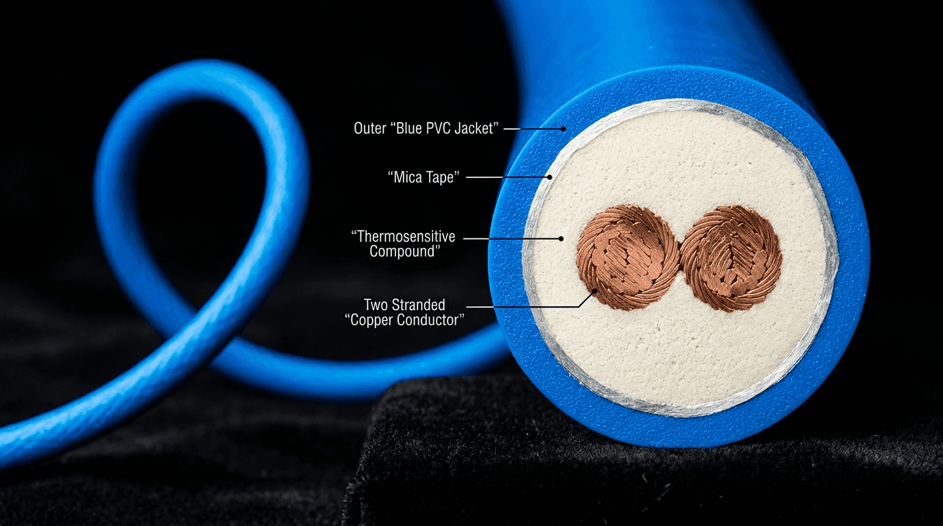
Because response time enters as L², halving the wall quarters the thermal lag. That is why our LHD line is extruded with a thermosensitive wall as thin as 0.10–0.15 mm — every tenth of a millimetre shows up in the alarm log. The compound that collapses to deliver the alarm — and the four-layer architecture wrapped around it — is the subject of our anatomy and trigger physics walk-through.
Worked example: two identical cables, compound wall 0.15 mm vs 0.30 mm. The ratio alone predicts tr,thick / tr,thin = (0.30/0.15)² = 4×. On a 20 K/min ramp from 25 °C, the thick-wall sample alarms 18–22 s later — often the difference between a contained and a catastrophic event.
Why every tenth of a millimetre shows up in the alarm log
Response time scales as L² (lumped-mass model). Halving the wall quarters the thermal lag — and the curve below shows why 0.15 mm vs 0.30 mm is a 4× jump, not a marginal difference.
Why not extrude every cable to 0.10 mm? Because thinner walls cost mechanical durability, dielectric margin and environmental ingress resistance. The design target is the thinnest wall that still clears the mechanical, dielectric and certification envelope.
6. Specification Playbook by Application
| Application | Insulation Stack | Response Target |
|---|---|---|
| Fire protection — warehouses, data centres, cable trays | Thermosensitive core + thin PVC or fluoropolymer jacket | < 10 s/m at activation |
| Process plants — chemical, mining, tunnels | FEP or PFA over thermosensitive core; MI in extreme zones | < 15 s on 20 K/min ramp |
| Appliance OEM — heaters, ovens, dryers (see OEM design note) | Silicone or FEP, set-point 105–170 °C | 10–30 s (appliance-dependent) |
| Motor winding / transformer protection | Silicone or polyimide film, Class-H rated | 5–20 s after hot-spot, 20,000 h at 180 °C |
7. Three Mistakes We See Repeatedly
- PVC jacket on a life-safety loop. Saves money in procurement, doubles response time in service.
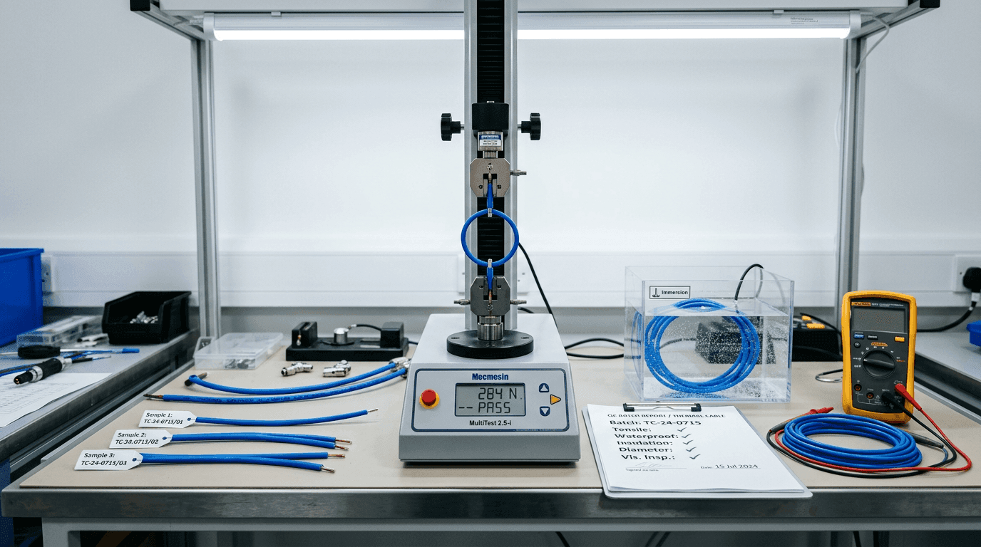
- Ignoring wall-thickness tolerance. A 0.15 mm wall at ±0.05 mm can behave like 0.20 mm — ~78% slower. Wall-thickness is parameter 6 in our nine-parameter QC pass — that is where this gets caught at acceptance.
- No aged-sample testing. Plasticiser migration can shift response >20% over the product life. Qualify on aged specimens.
8. Closing Thought
Insulation is not packaging. Diffusivity, wall thickness and compound kinetics together set the number on the alarm log — and because L enters squared, wall thickness is the most powerful single lever the cable designer has. If your loop has to alarm in under 10 s, or hold its response after two decades in a harsh plant, send us the application and response target. We'll come back with a material, a wall-thickness call-out and a validation sample.
FAQ — Engineering Response Time
What actually governs the response time of a thermosensitive cable?
The dominant variables are the insulation's thermal diffusivity (k / ρc) and the wall thickness squared. Compound kinetics — how sharply the thermosensitive layer collapses around its activation point — then modulates the observed alarm time.
Which construction gives the fastest alarm at the activation point?
A thin-wall thermosensitive compound core (0.10–0.15 mm) jacketed with a thin fluoropolymer skin (FEP or PFA) typically delivers sub-10-second-per-metre alarm at or above the rated activation temperature.
How sensitive is response time to wall thickness?
Very. To first order, lumped-thermal-mass analysis gives a response time that scales with L². Doubling the insulation wall from 0.10 mm to 0.20 mm quadruples the thermal lag for the same compound.
Is maximising thermal conductivity the primary design objective?
No. Conductivity accelerates heat transport, but the insulation also has to hold dielectric integrity, pass aging tests and collapse repeatably at the rated activation point. The correct optimisation balances diffusivity, kinetic sharpness, mechanical endurance and environmental resistance.