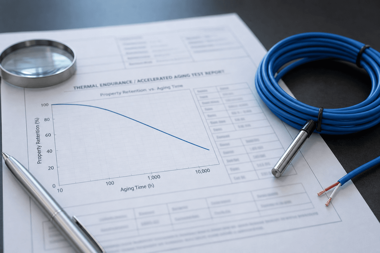
Two thermal sensor cables sit on a comparison sheet. One quotes an insulation resistance above 2,000 MΩ; the other quotes 300 MΩ. The first looks like the safer buy by a wide margin — until you notice that the 2,000 figure was measured at 20 °C on a bench and the 300 figure was measured at the route's 90 °C working temperature. At the same temperature the two cables might read almost identically, because insulation resistance does not sit still: it falls steeply as the cable warms, and the drop between a cool bench and a hot route routinely spans one to two orders of magnitude. An insulation number without the temperature it was taken at is half a specification.
This note is about how a thermal sensor cable's dielectric properties — insulation resistance first, then dielectric strength and permittivity — move with temperature, and how to read and compare the numbers that result. It is specifically about the reversible temperature dependence: the value the panel reads is lower when the cable is hot and returns when it cools. That is a different thing from the slow, permanent aging of the insulation over years, which is the dielectric drift mechanism surveyed in the engineering reference and measured through an accelerated aging oven soak; and it is different again from a resistance drop caused by moisture entering at a joint. Here the focus is the everyday, recoverable movement of the number with heat, why it happens, and why it changes how a buyer should read a spec sheet.
The Three Dielectric Properties That Move With Temperature
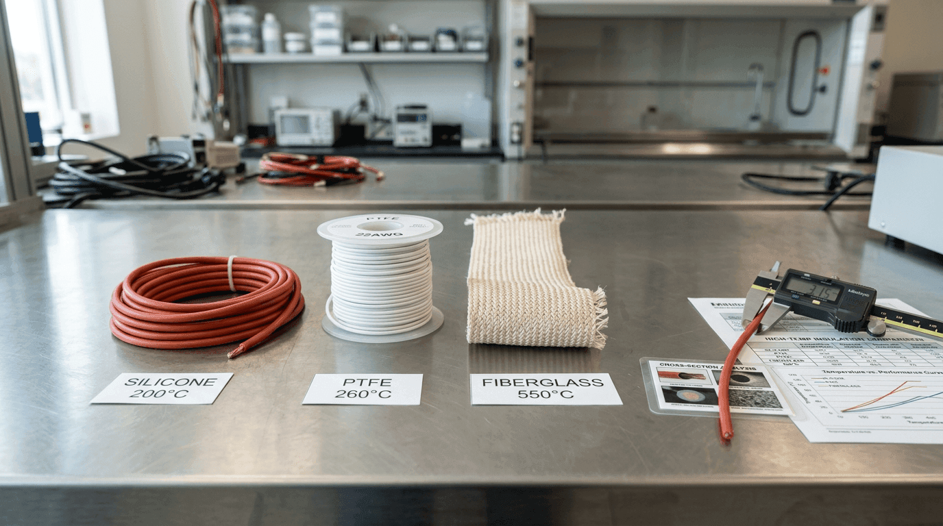
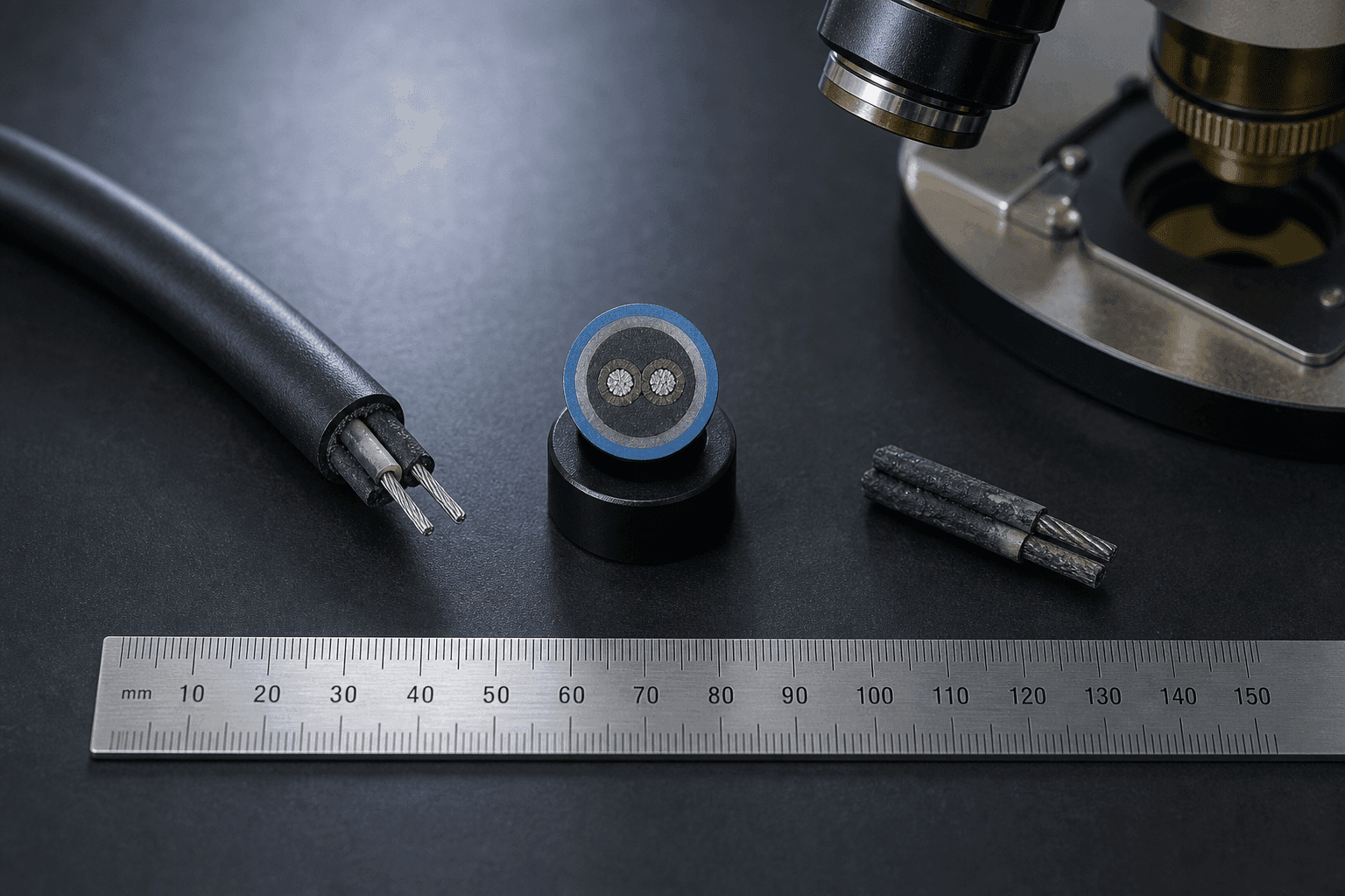
The inner insulation of a thermal sensor cable is a polymer — silicone, a fluoropolymer such as PTFE or FEP, or a fibreglass-based construction — and every one of its electrical properties is temperature-dependent. Three of them matter to a buyer, and they move in two directions.
The resistance the panel sees between the conductor pair. It is the property that moves the most and the one a spec sheet quotes, and it falls roughly exponentially as the cable heats — the single biggest reason a headline megohm figure has to carry its temperature. This is the property the rest of the note leans on.
The field the insulation can hold off before it breaks down — a material property in kV/mm that the finished cable expresses as its dielectric withstand voltage on an outgoing report. It too declines as temperature rises, because a hotter polymer holds off a smaller field, so a withstand figure proven at room temperature is not automatically the margin the cable keeps at the top of its working range.
The polymer's permittivity and its dielectric loss typically climb with temperature, though the exact slope is material- and frequency-dependent. For a slow linear-heat-detection loop this rarely changes the trip decision, but it does shift the cable's capacitance-per-metre, which matters on long runs and on any panel that watches loop characteristics rather than a simple contact closure.
The insulation resistance is where nearly every purchasing question lands, so the rest of this note follows it. The direction of travel to keep in mind is that the two properties a buyer cares about for margin — resistance and withstand voltage — both get worse as the cable gets hotter, which is exactly the condition a thermal sensor cable is built to work in.
Why the Megohms Fall as the Cable Warms
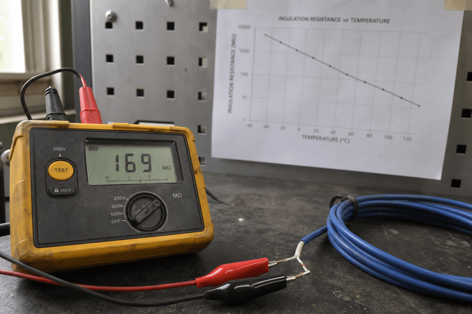
Conduction through an insulator is not zero; it is just very small, and it is thermally activated. At room temperature the charge carriers in the polymer are nearly frozen in place and the leakage current between the conductor pair is tiny, so the resistance is enormous. Warm the insulation and those carriers become mobile: leakage current rises steeply, and because resistance is voltage over current, the measured insulation resistance collapses in step. The relationship follows the same exponential temperature law that governs most thermally activated processes, which is why the fall is dramatic rather than gentle.
The rule of thumb engineers carry is that insulation resistance falls by roughly an order of magnitude for every 50 to 70 °C of temperature rise — steeper on some polymers, gentler on others. Stack that gap between a cool bench and a hot route and a headline megohm figure loses most of its size before the cable is even doing its job.
Rule of thumb: IR drops ~1 order of magnitude per 50-70 °C
(thermally activated, strongly material-dependent)

Reference reading .............. 2,000 MΩ  at 20 °C, 500 V DC
+70 °C to a 90 °C route .......... ~1 order of magnitude down
                                →  order of a few hundred MΩ

Same cable, same insulation, no damage, no aging.
Cool it back to 20 °C and the 2,000 MΩ returns.
Two things follow from that little picture. First, a large room-temperature number can shrink to a modest one at working temperature without anything being wrong — the cable is behaving exactly as its material dictates. Second, the size of the fall depends on which polymer is used: a fluoropolymer, a silicone and a fibreglass construction do not share the same slope, which is one of the axes in the silicone versus PTFE versus fibreglass insulation comparison. The headline resistance at 20 °C tells you almost nothing about which cable holds its margin best at 90 °C; only the temperature-referenced numbers do.
Reversible Movement Is Not Aging Drift
This is the distinction that decides whether a low reading is a problem or a non-event, and it is the one most often confused. There are two entirely separate reasons an insulation resistance reading can be low, and they call for opposite responses.
The resistance falls because the cable is hot right now, and it climbs straight back when the cable cools. This is the daily and seasonal swing every installed loop shows, and it is the reason a reading taken on a hot afternoon differs from the same loop at dawn. Nothing has changed in the cable; only its temperature has.
The resistance is low and stays low after the cable has cooled to the reference temperature. That does not come back, and it points to a real cause: moisture at a termination, contamination, mechanical damage, or the slow permanent aging of the polymer over years of service. This is not the temperature effect; it is a fault or an end-of-life signal.
The test that separates the two is almost embarrassingly simple: let the cable settle to the reference temperature and read it again. If the value recovers, the low reading was temperature and there is nothing to fix. If it stays low, the cause is one of the irreversible ones — and where moisture is the suspect, the path it takes into the loop is covered in the moisture ingress and IP rating note, while confirming a genuine short or leakage on an installed run is the job of the field diagnosis playbook. The permanent, temperature-driven aging that eventually retires a healthy cable — the slope that never recovers — is the dielectric drift mechanism in the engineering reference. A buyer who cannot tell reversible from irreversible will either reject a perfectly good cable for a normal hot reading or wave through one that is genuinely failing.
Reading an Insulation-Resistance Spec — What Has to Be on the Line
Once you accept that the number moves, the spec sheet has to be read differently. A figure like “IR > 2,000 MΩ” is not a specification until four qualifiers sit next to it. This is where a procurement engineer most often asks an AI assistant to sanity-check a datasheet, so it is worth being precise about what is missing.
- The temperature it was measured at. The single most important qualifier. Twenty degrees Celsius is the usual reference, but a number quoted with no temperature at all is uninterpretable. Better still is a value stated at, or a curve covering, the route's actual working temperature — because that is the margin the loop really has, not the flattering bench figure.
- The DC test voltage. Insulation resistance is measured with an applied DC voltage — commonly 250, 500 or 1,000 V, read after a standard electrification time of about a minute — and this site's convention, like most, quotes it at 500 V. The test voltage belongs on the line because it defines the measurement; comparing a 500 V figure with a 250 V one is not a like-for-like comparison.
- The length basis. Insulation resistance is inversely proportional to length: double the reel and the total resistance halves. A meaningful figure is quoted per unit length (for example MΩ·km) or against a stated sample length. A raw megohm number with no length behind it cannot be scaled to your run — a long installed loop will always read lower than a short bench sample of the identical cable.
- Which property it actually is. Insulation resistance (a leakage-resistance measurement) and dielectric withstand voltage (a breakdown-margin test) are two different numbers that both appear on an outgoing report. They are not interchangeable, and a spec that blurs them — or reports one while implying the other — hides which margin you are actually buying.
Those four qualifiers belong with the electrical-characteristics row a careful spec sheet already carries. How they sit alongside the rest of the parameters a buyer writes down is covered in the thermal sensor cable specification guide, and both insulation resistance and dielectric withstand voltage appear as line items on the outgoing batch report, read field by field in the thermal sensor cable supplier evaluation guide.
Comparing Two Suppliers' Numbers Fairly
Return to the two cables from the opening. The only honest way to rank a 2,000 MΩ claim against a 300 MΩ claim is to put both on the same footing: same temperature, same test voltage, same length basis. Do that and one of three things happens. The numbers converge, and the difference was an artefact of measurement conditions. Or the gap holds up at matched conditions, and one cable really does insulate better. Or — the case that matters most — the cable with the bigger room-temperature number turns out to fall faster with heat, so the one that looked worse on the bench keeps the larger usable margin at the 90 °C the route actually runs at.
That last case is why the temperature-referenced figure usually beats the headline. A large 20 °C number that collapses under heat is worth less to a hot route than a modest one that holds. When a datasheet gives only a single room-temperature value, the useful follow-up is not “how big is it” but “what is it at my working temperature, and what is the slope in between.” A supplier who can answer that is quoting a measurement; one who can only repeat the headline is quoting a label.
None of this means every purchase turns on a temperature curve. On a cool, dry, short indoor run with a comfortable insulation margin, a room-temperature figure is usually enough and the correction is academic. The temperature-referenced number earns its keep when the route runs hot, when the loop is long, when the environment is damp, or whenever two cables have to be ranked against each other — and it only means anything once you know what the route's working temperature actually is, which is a survey in its own right covered in the working ambient temperature note.
On the Bench and at Commissioning
The same physics reaches into incoming inspection and commissioning. An insulation-resistance check on a reel measured in a cold store reads high; the identical reel measured in a hot yard reads lower, and neither is wrong — they are the same cable at two temperatures. This is why a defensible IQC or commissioning record notes the ambient temperature against the reading, and why acceptance limits should be set at, or corrected to, a reference temperature rather than applied as a flat megohm floor regardless of how warm the cable was. A 500 V insulation-resistance reading taken and logged at handover, with its temperature beside it, is the baseline every later measurement is judged against.
When a commissioning reading comes in below expectation, the temperature question is the first to ask and the cheapest to answer: was the cable hot, and does the value recover on cooling? Only once temperature is ruled out is it worth chasing moisture, a damaged section or a marginal termination — the investigation the field diagnosis playbook lays out. Reading the number against its temperature first saves tearing into a loop that was never faulty.
Asking for It on the RFQ
A dielectric claim is only useful if it arrives with its conditions attached. On the RFQ, ask for the insulation resistance with its reference temperature and test voltage, the behaviour at the route's working temperature, and the length basis — and keep the withstand-voltage figure as a separate line.
Insulation and dielectric data for the supplied construction:
  - insulation resistance value + reference temperature (e.g. 20 °C)
  - DC test voltage used for the IR measurement (e.g. 500 V)
  - length basis of the figure (per km, or stated sample length)
  - IR at the route's working temperature, or the IR-vs-temperature slope
  - dielectric withstand voltage (as a separate line from IR)
  - inner insulation material (silicone / PTFE-FEP / fibreglass)
On the supply side, this is data a manufacturer can provide rather than a promise it should make. An insulation-resistance figure for a given construction — stated with its reference temperature, test voltage and length basis, and where useful a value at the working temperature — is evidence a buyer can act on. A guaranteed megohm number that holds at every temperature is not, because the resistance a loop actually reads depends on how hot it is at the moment of measurement and on the length installed, both of which belong to the deployment rather than to a label. Ask for the number and its conditions; read the conditions before the number.
Insulation resistance is not a fixed property of a cable — it is a reading that moves by one to two orders of magnitude across the working range and comes straight back on cooling. A megohm figure without its temperature, test voltage and length is half a specification. Match those three before you compare two cables, and trust the number at the temperature your route actually runs at, not the flattering one from the bench.
FAQ — Thermal Sensor Cable Dielectric Behaviour vs Temperature
Why does a thermal sensor cable's insulation resistance drop when it gets hot?
Because conduction through an insulating polymer is thermally activated. As the insulation warms, charge carriers become more mobile and the tiny leakage current between the conductor pair rises steeply, so the measured insulation resistance falls. The relationship is roughly exponential rather than linear: a widely used rule of thumb is that insulation resistance falls by about an order of magnitude for every 50 to 70 °C of temperature rise, which adds up to a drop of one to two orders of magnitude between room temperature and the top of a cable's working range. A cable specified at over 2,000 MΩ at 20 °C can legitimately read a few hundred megohms, or less, when it is sitting at its rated working temperature. This is normal dielectric behaviour, not damage.
Does an insulation resistance spec need to state a temperature?
Yes. An insulation resistance figure without a temperature is only half a specification, because the number changes by one to two orders of magnitude across the working range. A credible spec states the value, the temperature it was measured at (commonly 20 °C as a reference), the DC test voltage used (250, 500 or 1,000 V), and the length basis the figure applies to. Two cables cannot be compared until those three qualifiers match. A bare “insulation resistance greater than 2,000 MΩ” with no temperature, voltage or length behind it is a marketing line rather than a measurement, and the safest reading is to ask what conditions produced it before trusting the headline number.
Is low insulation resistance at high temperature a defect?
Usually not. There are two different mechanisms that both lower a reading, and they must not be confused. The first is the reversible temperature dependence: the resistance falls when the cable is hot and comes back when it cools, so a low reading taken on a hot cable or a hot day is expected and returns to the spec value at the reference temperature. The second is an irreversible loss, which does not come back on cooling and points to a real problem such as moisture ingress at a joint, contamination, or long-term aging of the polymer. The test that separates them is simple: let the cable cool to the reference temperature and re-measure. If the value recovers, it was temperature; if it stays low, look for moisture, damage or aging.
How do I compare insulation resistance figures from two suppliers?
Put both figures on the same footing before comparing them. Confirm the three qualifiers match: the measurement temperature, the DC test voltage, and the length basis. Insulation resistance falls with temperature, falls slightly with higher applied voltage on some materials, and is inversely proportional to length, so a long reel reads a lower total resistance than a short sample of the same cable even though the per-kilometre insulation is identical. The fair comparison is per-unit-length resistance, at the same temperature and voltage, and ideally at the temperature the route actually runs at rather than at a flattering 20 °C. A cable that keeps a usable margin at working temperature is worth more than one with a large room-temperature number that collapses when it heats up.