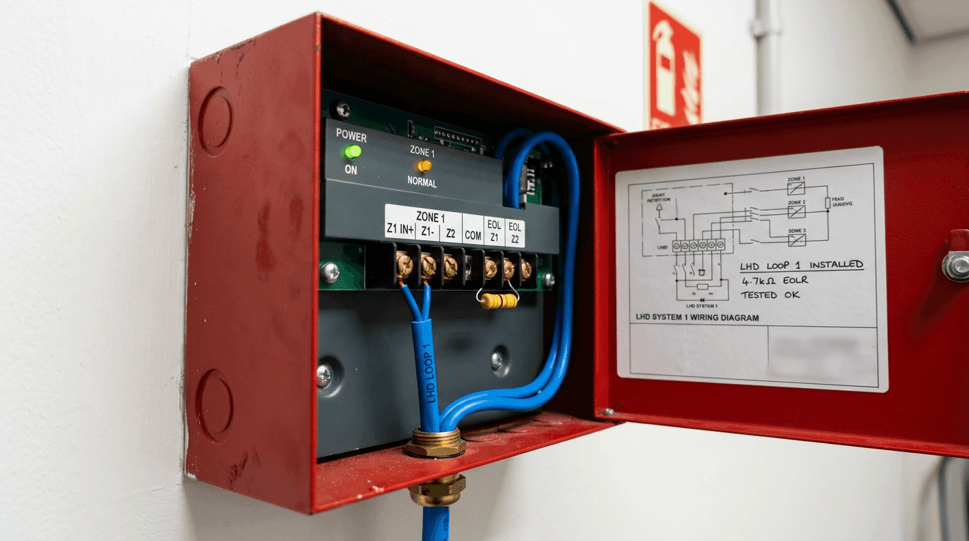
When a linear heat detection loop drops into alarm, the control panel gives you the result, not the reason. To the panel, a real thermal activation, a crushed jacket, a wet splice and a conductor bridge inside a termination can all look like the same low-resistance event. That is why LHD cable short circuit diagnosis has to start at the cable, not at the panel display.
This is the compact method our field engineers use before recommending replacement. It is written for fire-protection contractors, maintenance teams and engineering buyers who need to know whether a failed run is a product issue, an installation issue or a site-environment issue. Which architecture is on the wall changes some of the diagnostic moves — see linear heat detection architectures compared if the loop in front of you is digital addressable or fibre-optic rather than fusible thermosensitive cable.
Do not replace a 400 m loop until you have proved where the low-resistance path is and what created it.
Start by Removing the Panel from the Test
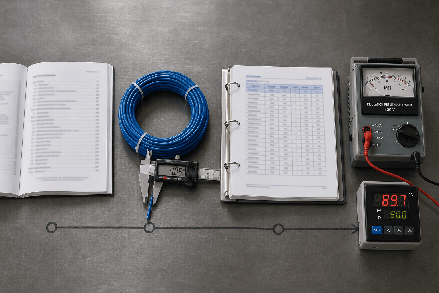
Panel supervision circuits, end-of-line components and surge modules can distort every reading. Isolate the loop first. Record the panel message and timestamp, de-energize the circuit, disconnect both conductors and the shield or drain, then measure the cable as a standalone component.
A handheld multimeter is enough for the first split: open circuit, normal loop resistance, or near-zero conductor-to-conductor resistance. It is not enough to identify the cause. A wet jacket can read like a hard short on one meter range and look completely different once a 500 V insulation resistance test is applied.
Build a Three-Reading Fault Signature
For a useful diagnosis, collect three readings on the same disconnected loop:
- Conductor-to-conductor resistance with a DMM. This tells you whether the alarm path is present.
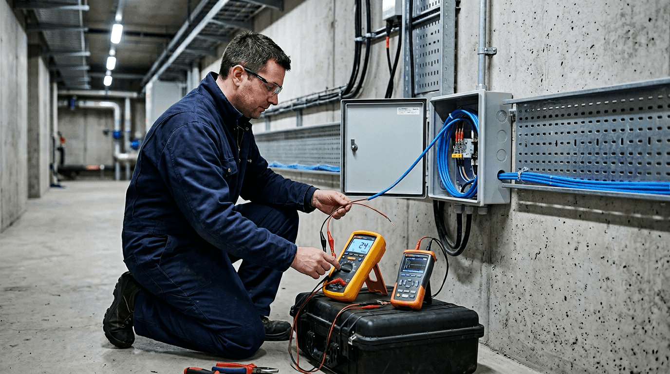
- Conductor-to-shield insulation resistance with a megohmmeter at 250 V or 500 V DC. This tells you whether the jacket or internal insulation is leaking.
- Distance to discontinuity with a TDR or by loop-resistance calculation. This tells you where to open the installation.
Those three numbers are more useful than any visual guess. A true activation usually gives a stable low conductor-to-conductor reading while insulation to shield remains high. A damaged cable often shows both low loop resistance and low insulation resistance, especially after rain, washdown or condensation.
Use Insulation Resistance as the Deciding Test
The megohmmeter is the instrument that separates electrical contact from insulation failure. On standard PVC, XLPE, silicone or fluoropolymer-jacketed thermal sensor cables, we interpret 60-second readings this way:
| 500 V DC Reading | Field Meaning | Next Action |
|---|---|---|
| > 100 MOhm | Insulation is healthy | Look for real activation or metallic contact inside a termination |
| 10-100 MOhm | Usually acceptable, but moisture may be starting | Repeat after drying and inspect glands or outdoor splices |
| 1-10 MOhm | Contaminated, damp or mechanically stressed insulation | Locate and isolate the suspect section |
| < 1 MOhm | Confirmed insulation fault | Repair or replace the failed segment after root-cause check |
The movement of the reading matters too. A healthy dielectric often climbs during the first minute as the cable charges. A wet or carbon-tracked path stays low from the first second. If the value jumps when the cable is flexed, expect a crushed point, pinhole, over-tight cable tie or conductor contact at a bend.
Separate Activation, Moisture and Mechanical Damage
A real thermal event leaves physical evidence: localized melting, heat discoloration, a process trip, fire exposure or a nearby over-temperature source. The low-resistance point does not recover after drying. The answer is replacement of the activated section with the same activation temperature and jacket system.
Moisture behaves differently. The loop may fail after rain, tunnel washing, HVAC condensation or a cold-room defrost cycle, then recover hours later. The usual entry points are glands, cut ends, sleeves without adhesive heat-shrink, and jacket nicks hidden at tray transitions. This is the most common cause of thermal sensor cable false alarm troubleshooting in humid coastal sites and washdown plants.
Mechanical damage is usually sharp and local. Look for crushed tray covers, tight bends below the cable minimum radius, scaffold impact, staples, overtightened stainless ties, or a cable pressed against a vibrating edge. In mining and chemical sites, abrasion plus chemical softening can make the same failure look like both a cut and a leak — the routing and jacket discipline that prevents this is documented in our LHD specification note for chemical and mining plants.
Locate the Fault Before Cutting Cable
A TDR is the fastest way to avoid opening every junction box. Set the velocity factor for the actual cable family, test from the panel end, then test from the far end. The two distances should add up close to the installed length. If they do not, you may have the wrong velocity setting, a hidden splice, or more than one fault.
Where TDR is not available, loop resistance can still narrow the zone. If the conductor resistance per meter is known, the measured resistance to the short gives an approximate distance — the same arithmetic behind the end-of-line resistor and loop-resistance calculation done at commissioning, run in reverse. It is less clean on mixed cable sizes or spliced runs, but it is still better than blind replacement.
Confirm by Section, Then Repair
Once the fault distance points to a tray bay or junction interval, open the nearest accessible point and split the loop. Measure each side. The faulty side keeps the low resistance or poor insulation value; the healthy side returns to normal. Only after that confirmation should the cable be cut.
- Remove the visibly damaged area plus margin on both sides.
- Keep the failed sample for supplier or lab review if the cause is unclear.
- Use matching cable construction: conductor, activation temperature, jacket chemistry and diameter.
- Seal splices with the correct heat-shrink, gland or junction hardware for the site environment.
- Re-test conductor resistance and insulation resistance before reconnecting the panel.
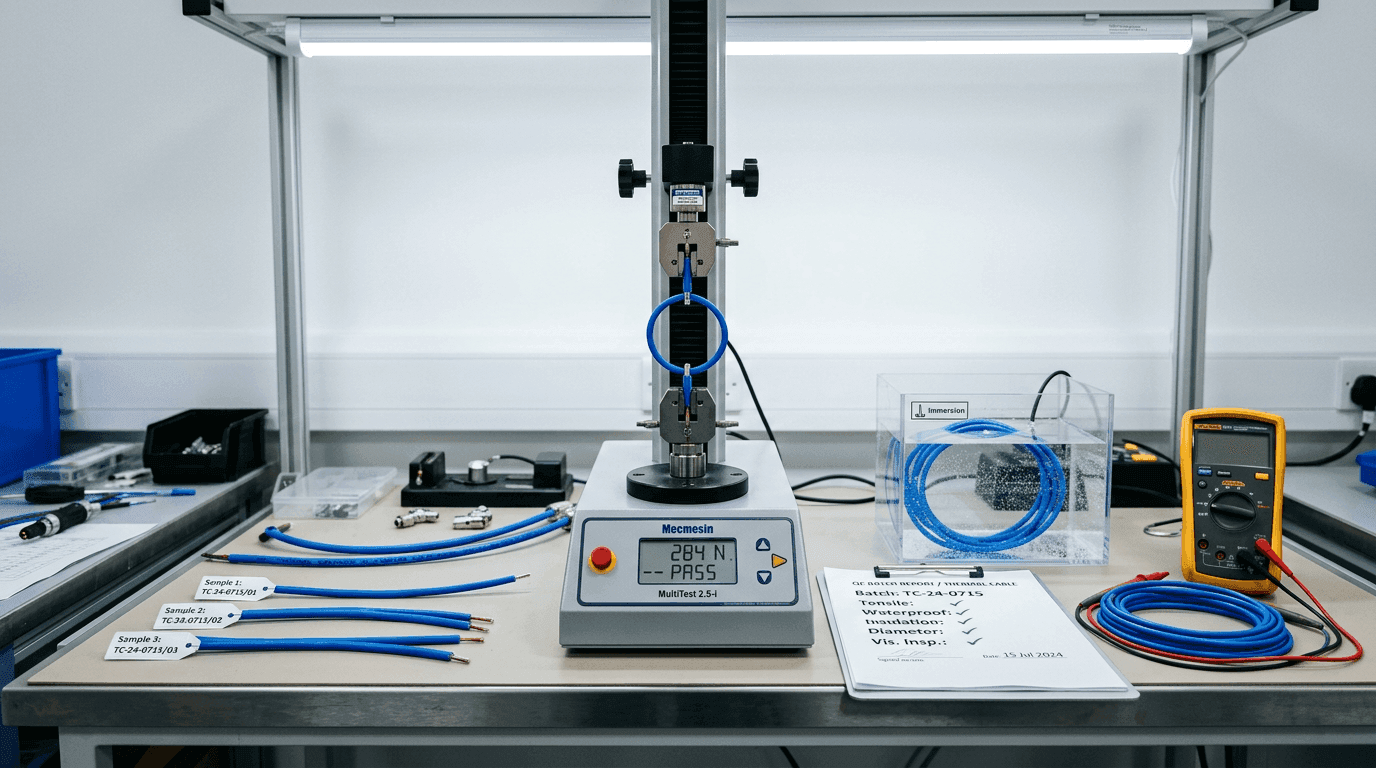
The final test values should go into the maintenance file. Six months later, that baseline often tells you whether a site has a recurring moisture path, an installation habit that damages cable, or a genuine need for a tougher jacket specification. When the pattern points to a recurring moisture path, the upstream fix is rarely a better cable alone — it is in how the IP rating is specified across the cable body, the terminations and the install, since water enters at the joints rather than the jacket. If the failure pattern points to the cable batch rather than the route, the next reference is the nine-parameter QC pass we run on every production batch — the parameters there are the ones an auditor should request when the site evidence does not add up.
When to Send the Sample Back
Most shorts are installation or environment related. But if several loops from the same batch show similar low insulation resistance, if the jacket cracks without visible mechanical stress, or if the fault does not match the site history, send us the sample with the test log and photos. Our engineering desk can compare the failure surface, jacket condition and production record, then recommend either a repair detail or a revised thermal sensor cable specification for the next purchase.
FAQ — Field Diagnosis of LHD Short Circuits
How can a field engineer tell whether an LHD cable alarm is a short circuit or real activation?
Start by disconnecting the cable from the panel and testing the loop directly. A real thermal activation normally shows a stable low conductor-to-conductor resistance while insulation resistance to shield remains high and the local cable body shows heat evidence. A field short often shows low insulation resistance to shield or drain, changes with movement or humidity, and points to a crush, cut, wet termination or failed splice.
What insulation resistance reading should make me suspect a damaged thermal sensor cable?
For standard installed runs, a 500 V DC megohmmeter reading above 100 MOhm is normally healthy. Ten to 100 MOhm deserves a repeat test on long or damp runs. One to 10 MOhm indicates contamination or moisture. Below 1 MOhm should be treated as a confirmed insulation fault until the damaged segment is isolated.
Can TDR locate a short in a linear heat detection cable accurately enough for repair?
Yes, if the cable velocity factor is set correctly and the reading is checked from both ends. TDR usually narrows the search to one tray bay, conduit section or junction interval. We still confirm by opening the nearest junction and measuring each segment before cutting cable.
Why do some thermal cable shorts disappear after the site dries out?
Intermittent recovery usually means moisture has entered through a gland, jacket nick or splice sleeve. Dry weather raises insulation resistance, but the entry path remains open. The cable should be repaired or partially replaced after the leak path is corrected.