A thermal wire that is specified properly should outlive the equipment around it. When one of ours comes back from the field in months instead of years, the reflex tends to be the same: blame the alloy. Ship the failed section back to the mill, demand a chemistry certificate, start a non-conformance. In our experience that is most often the wrong investigation. In the failure analyses our lab runs — on our own wire and on returns from competitor spools — the chemistry is within specification in more than nine samples out of ten. The wire did not fail because the metal was wrong. It failed because an oxidation mechanism was eating the protective element faster than the alloy could replenish it.
This note is a metallurgist's tour of those mechanisms. Once you see how protective oxides actually work — and the five specific ways they collapse — you can stop the ninety-percent case of premature burnout before the wire is even on the drum.
1. The Protective Oxide Is Not the Wire
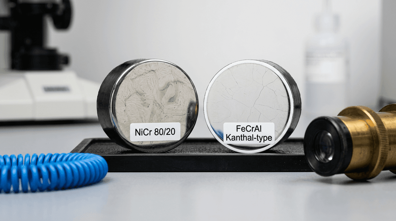
Every serious high-temperature alloy owes its life not to the metal itself but to a ceramic skin that forms on the first hot cycle. On Nichrome (Ni80Cr20) that skin is a dense layer of chromium oxide, Cr2O3. On FeCrAl (Kanthal and its variants) it is aluminum oxide, Al2O3. Both are glass-like, adherent and — most importantly — thousands of times slower to transport oxygen than the bare metal is to react with it. That oxide is the wire's only real defence.
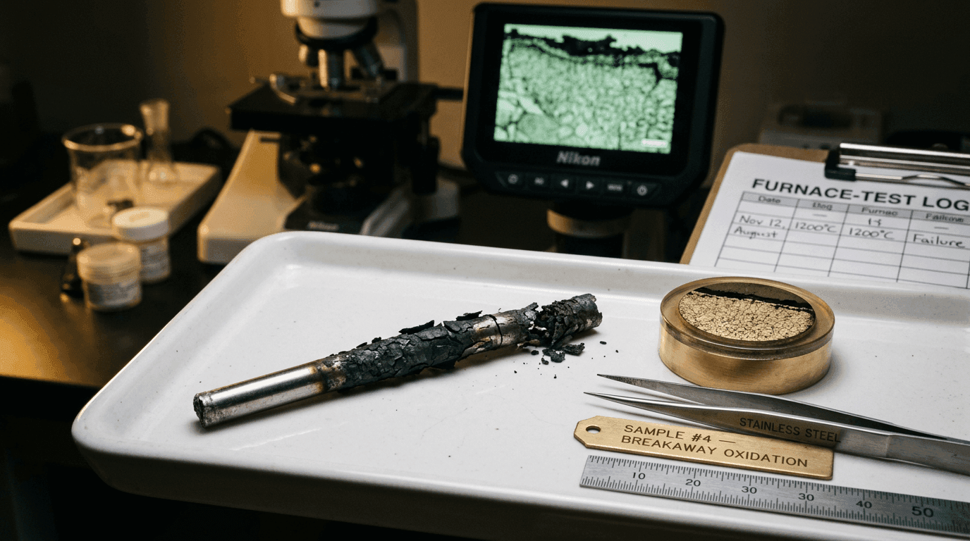
It is also finite. Every hour at temperature the alloy burns a little of its chromium or aluminum to maintain the layer. Re-oxidisation after a scrape, a crack from thermal expansion or a handling nick — each event consumes more. The alloy contains a fixed reservoir of the protective element: around 20% chromium in Ni80Cr20, around 5% aluminum in Kanthal A1. The instant the local reservoir drops below a critical threshold, the ceramic cannot reform. What grows next is iron oxide or nickel oxide — both of which are porous, cracked and non-protective. From that moment the wire is in breakaway oxidation: the scale thickens fast, flakes off, the cross-section collapses, resistance climbs, local temperature climbs with it, and the element burns through.
A resistance wire does not die when its metal runs out. It dies when its protective element runs out — typically years before the metal itself is gone.
Every one of the five practical failure modes below is a variation on a single theme: something is either consuming the chromium or aluminum reservoir faster than normal, or destroying the oxide layer directly so the reservoir has to keep rebuilding it. Fix the mechanism and you recover the life.
2. Cause A — Chronic Over-Temperature (Usually Geometric, Not Thermal)
Oxidation is Arrhenius. It does not rise linearly with temperature; it rises exponentially. A useful rule for both Nichrome and FeCrAl is that the oxidation rate roughly doubles for every 50 °C of extra temperature. Running the wire 100 °C above its rating consumes protective element at four times the rate, 150 °C above at eight times, 200 °C above at about sixteen times. The reservoir the alloy was designed to last twenty years will be gone in one or two.
The sneaky version of this mistake is not a controller set-point error — it is a geometric one. Under operating power the wire surface sits hotter than the air around it, because power has to flow out of the wire by radiation and convection. On elements with a high surface watt load the gradient can reach 100–150 °C. A furnace nameplate of 1050 °C can mean the wire surface is sitting at 1200 °C, well above the continuous ceiling for Nichrome (1150 °C) and squarely in breakaway territory.
Prevention. Rate the wire against its own surface temperature, not the chamber air temperature. Hold 50–100 °C of headroom. Our engineering note on the conductor alloy framework for thermal sensor cables covers the same metallurgy from the cable conductor's side; our cable specification mistake article walks through the route, jacket and termination decisions that surround it.
3. Cause B — The Wrong Atmosphere for the Alloy
The protective oxide is a chemical equilibrium. Change the gas composition and the equilibrium shifts — sometimes enough to dismantle the layer entirely. There are five atmospheres that regularly destroy wire early, and each one has a different "correct" alloy:
- Reducing or vacuum atmospheres (H2, cracked ammonia, CO). FeCrAl cannot regenerate its Al2O3 without oxygen. In a hydrogen-rich brazing furnace a FeCrAl element can strip its protective layer in days. Nichrome is more tolerant here because its nickel-rich matrix is already noble enough; this is the textbook case where Nichrome is the right pick.
- Sulfur-bearing atmospheres (H2S, SO2, crude-combustion gases). Sulfur forms a low-melting eutectic with nickel — Ni3S2 melts at roughly 645 °C. The result is that a Nichrome element in a sulfur atmosphere literally dissolves at the grain boundaries. FeCrAl, containing no nickel, walks through sulfur atmospheres untouched.
- Halogens (Cl2, F2, HCl, HF). Halogens attack the oxide directly, turning the protective ceramic into volatile metal halides that evaporate off the surface. Even trace halogens from PVC cable offcuts burnt in a nearby furnace can trigger deep pitting. No common heating alloy is immune; for halogen-rich atmospheres the right answer is usually a ceramic-insulated heater with a sheath, not a bare coil.
- Carburising atmospheres (carbon-rich furnace gases, carbon dust in furnaces melting aluminium-bronze, etc.). Carbon diffuses in and forms chromium carbides at the grain boundaries. The grain interiors are then chromium-starved and can no longer grow Cr2O3. The wire looks fine externally until suddenly it is brittle and spalling.
- Nitrogen-bearing reducing atmospheres in the 800–1050 °C window. This is the classic green rot case in Nichrome: nitrogen and carbon combine with chromium inside the grain boundaries, producing the characteristic green internal discoloration and catastrophic embrittlement. FeCrAl does not suffer green rot.
Prevention. Write the atmosphere down in the specification — worst case, not nominal. Match the alloy to that atmosphere first, then verify temperature. The NiCr vs FeCrAl decision matrix maps atmospheres to alloys in one page.
4. Cause C — Cycling and Oxide Spall
A wire held at 1000 °C continuously grows its oxide once and stops. A wire that heats from 25 °C to 1000 °C every morning and cools back at night damages that oxide every time. The reason is thermal expansion mismatch: the metal and the oxide shrink at different rates. Tensile stress builds in the ceramic on cooling; large enough stress and the scale cracks or pops off entirely.
The next heat-up finds bare metal. The alloy re-oxidises, consuming more protective element, and the clock restarts shorter than it started. Cyclic damage accumulates: a typical batch-furnace element delivers only 30–60% of the life a continuous furnace element does at the same peak. FeCrAl is hit harder than Nichrome because Al2O3 is more brittle and more prone to spalling than Cr2O3.
Prevention. If cycling is structural — a heat-treat shop, a bakery oven, a solder reflow line — rate the wire one step up the alloy ladder, as if the continuous temperature were higher. Avoid forced cooling on the element; a slow natural cool costs half an hour of cycle time and buys years of element life.
5. Cause D — Hot-Zone Contamination
This is the cause we see most often and the one maintenance engineers most often dismiss. Minute amounts of the wrong substance, riding the airflow into the hot zone, strip the oxide locally and seed the hotspot that burns the element through.
The offenders are not exotic:
- Silicone oils and anti-seize compounds. Silicone decomposes to SiO2 at temperature and poisons Al2O3 layers — a fatal combination on FeCrAl.
- Brazing and soldering flux residues, especially fluoride-based formulations. These are halogen sources in disguise.
- Chloride-bearing dust. Concrete grinding, rock-salt de-icing, even nearby coastal air. Chloride accelerates oxidation at any temperature and pits the surface.
- Zinc, lead and tin vapour from galvanised parts or tin-plated hardware. Low-melting-point metals embrittle Nichrome through intergranular penetration — one zinc-plated bracket mounted inside a hot chamber can kill an entire element bank.
- Refractory outgassing. A new ceramic fibre insulation board often releases sulfur, alkali or organic binder gases for the first dozen hours of service. Fire the refractory before you install the element.
- Handling oils and fingerprints. On massive furnace elements this burns off harmlessly, but on fine-gauge thermal sensor wire it leaves carbon residue that will carburise a local patch.
Prevention. Treat the hot zone the way a semiconductor fab treats a reticle. Clean gloves on installation, flux-free joining methods, no PVC or silicone anywhere the chamber breathes, and a shakedown fire on new refractory before any element sees real duty.
6. Cause E — Surface Watt Load and Local Hotspots
The fifth mechanism is the one that amplifies every other cause. Surface watt load — watts dissipated per cm2 of wire surface — decides how much the wire overshoots its surroundings. Push it high and the wire cannot shed heat fast enough; it settles at a temperature well above the chamber, and all four mechanisms above accelerate together.
Local hotspots are worse than a uniformly high load. Any coil point that touches a support, any bend radius that concentrates resistance per unit length, any section next to a failing insulator — all run 100–200 °C hotter than the rest of the element. Oxidation at that spot runs at several times the bulk rate. The cross-section thins locally, resistance rises locally, that section gets hotter still, and the positive-feedback loop closes on a burn-through. The rest of the wire can still look new when the end comes.
Prevention. Calculate surface load against the supplier's published ceiling for your temperature. Inspect the geometry: no point contacts with supports, no sharp bend radii inside the hot zone, no cracked ceramics. Replace supports before they sag onto the wire.
7. Reading the Evidence — A Field Diagnostic Table
When a failed element comes back, the visual signature is usually enough to pin the mechanism. Confirm with a metallographic cross-section, but start here:
| Visual Signature | Most Likely Mechanism |
|---|---|
| Uniform grey-green scale; wire thinned evenly along full length | End of rated life OR chronic over-temperature — check set-points and surface load |
| Thick black flaking scale, brittle wire, heavy diameter loss | Breakaway oxidation after Cr/Al depletion — usually high surface load or excessive cycling |
| Internal green discoloration, wire shatters on bending | Green rot in Nichrome — nitrogen or carbon in a reducing atmosphere |
| Melted bead at burnout point, wire runs through metal instead of oxide | Nickel-sulfide attack — sulfur contamination of a Nichrome element |
| Clean wire except a single hotspot; rest of element looks new | Point contact, insulator failure or local contamination at that spot |
| Random pitting; deep holes with smooth walls | Halogen attack — chlorine or fluorine in the atmosphere |
| Grey brittle surface, carburised cross-section under microscope | Carburisation — carbon-rich atmosphere or carbon residue from handling |
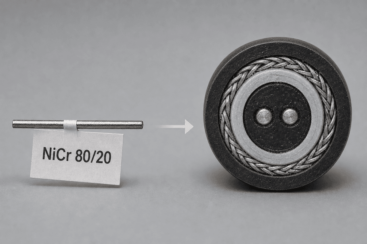
8. Oxidation in Thermal Sensor Cables — A Slower Clock
All the above applies to elements intentionally run hot. In thermal sensor cables and LHD loops the wire sits at ambient temperature for 99.9% of its life. In principle, oxidation should be irrelevant — yet we still see slow failures in the field.
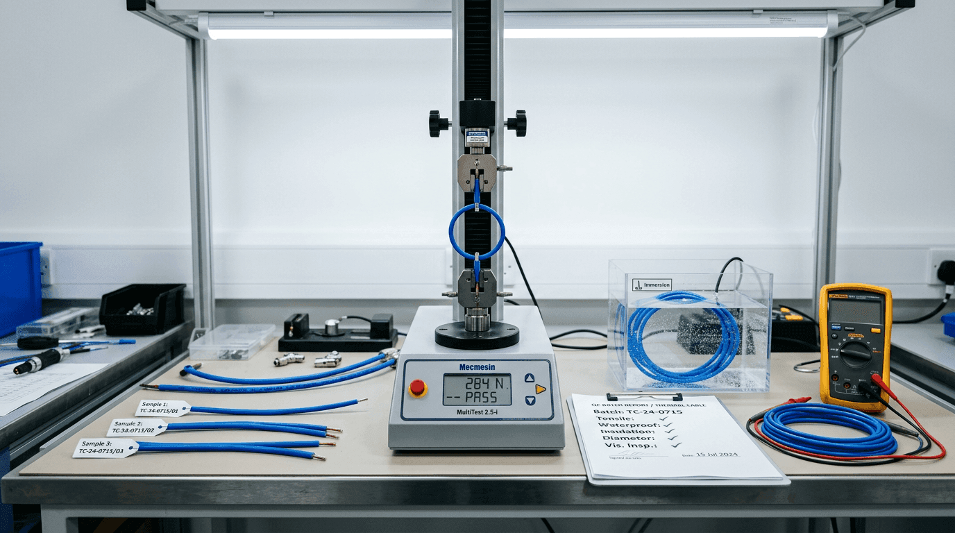
The driver here is not temperature but atmosphere ingress. A damaged jacket lets moisture, salt mist, hydrogen sulfide or chloride vapour migrate down the cable over a decade. The wire slowly corrodes at ambient, resistance drifts up, and eventually the zone-resistance reading at the panel drifts out of calibration. The cable looks fine externally; it simply stops detecting correctly. The countermeasure is exactly the same as for heating elements — match the conductor alloy to the likely ambient chemistry, and trust the jacket and gland seal to keep the worst of it out. The cable platforms we ship for these duties — LHD Series for fire-panel loops and TS Series for OEM cut-off paths — are built on Ni80Cr20 conductors with jacket systems specified against the audited atmosphere; both ship with the per-batch QC report needed to defend the loop at a 10-year inspection.
9. Life-Extension Checklist
Before any new thermal-wire specification leaves our engineering desk, these seven items have to be signed off. It is a short list, and every item on it is a line drawn around a root cause described above.
- Atmosphere classified (oxidising / reducing / vacuum / sulfur / halogen / carbon) — alloy selected accordingly.
- Continuous wire-surface temperature at least 50–100 °C below rated maximum.
- Surface watt load calculated and within the alloy's published limit at the target temperature.
- Duty cycle assessed — cyclic service derated by one alloy step.
- Hot zone contamination sources eliminated: no silicone, halogen, galvanised or fluxed parts.
- Element geometry audited: no point contacts, no sharp bends, no sagging supports.
- Material certificate on file: chemistry and resistivity traceable to melt lot.
10. How We Help
Our metallurgy lab runs failure analysis on returned thermal wire and LHD cable samples — SEM cross-section, EDS chemistry mapping, oxide-thickness profiling and localised microhardness — and turns the findings into a corrected specification for the next production run. If you are seeing premature oxidation, drift in detection-zone accuracy, or unexplained hotspots on deployed wire, send a failed sample and a description of the operating conditions. Turnaround on the root-cause report and revised wire spec is subject to project scope and engineering review.
FAQ — Thermal-Wire Oxidation Failure
Is premature thermal-wire burnout usually a bad alloy batch?
Very rarely. In over 90% of the failure analyses we see, the chemistry of the wire is within specification. The root cause is most often an oxidation mechanism the specification did not account for: atmosphere, surface watt load, thermal cycling, hot-zone contamination or simple over-temperature service.
What is breakaway oxidation in practical terms?
Once the alloy has consumed enough of its protective element — chromium in Nichrome, aluminum in FeCrAl — to fall below the critical reservoir, the dense protective oxide can no longer rebuild. Iron and nickel oxides then grow freely, the scale spalls, the wire diameter collapses and resistance drifts upward until the element burns through.
Why does a cyclic furnace wear out elements faster than a continuous one?
Every cool-down cracks the oxide layer because the alloy and the scale contract at different rates. Heat-up then re-oxidises the exposed metal and consumes more chromium or aluminum. Cyclic elements typically reach only 30–60% of the service life of a continuous element at the same peak temperature.
Do oxidation problems exist in thermal sensor cables that never run hot?
Yes. Sensor cables sit at ambient for most of their life, but moisture, chloride or H2S ingress through a damaged jacket can attack the internal wire slowly over years. The failure mode is resistance drift rather than burnout, but detection accuracy degrades the same way.