On a thermal sensor cable spec sheet, the activation class gets all the attention and the tolerance band gets a default. The class is the number a buyer argues over — 88 or 105, standard or custom. The band is usually whatever the catalogue prints next to it: ±15 K. Custom activation tolerance for thermal sensor cable is the decision that starts the moment someone asks whether that default is tight enough, and it is a different decision, with a different cost, from choosing the class itself.
This note sits one level below activation temperature selection. That page settles which class fits the route and whether a custom set-point earns its cost; this one assumes the class is fixed and goes into the tolerance number — what the band physically represents, how tight a factory can actually hold it, what tightening costs, where a tight band earns its place, and how to write and verify it. The line it becomes on the procurement document is Field 4 of the RFQ template; the cable families it applies to — LHD for linear heat detection and TS for in-device thermosensitive cut-off — are set out on the cable series page.
The Band Is a Distribution, Not a Per-Metre Promise
The first thing to fix is what a tolerance band on a thermal sensor cable actually means. It is not a promise that every metre trips at exactly the class. The activation point comes from a thermosensitive compound, and the compound's trip temperature scatters a little from batch to batch and along a run. The band is the window that scatter has to fit inside — a production distribution, not a single fixed value.
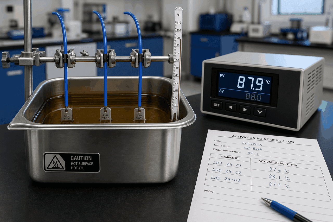
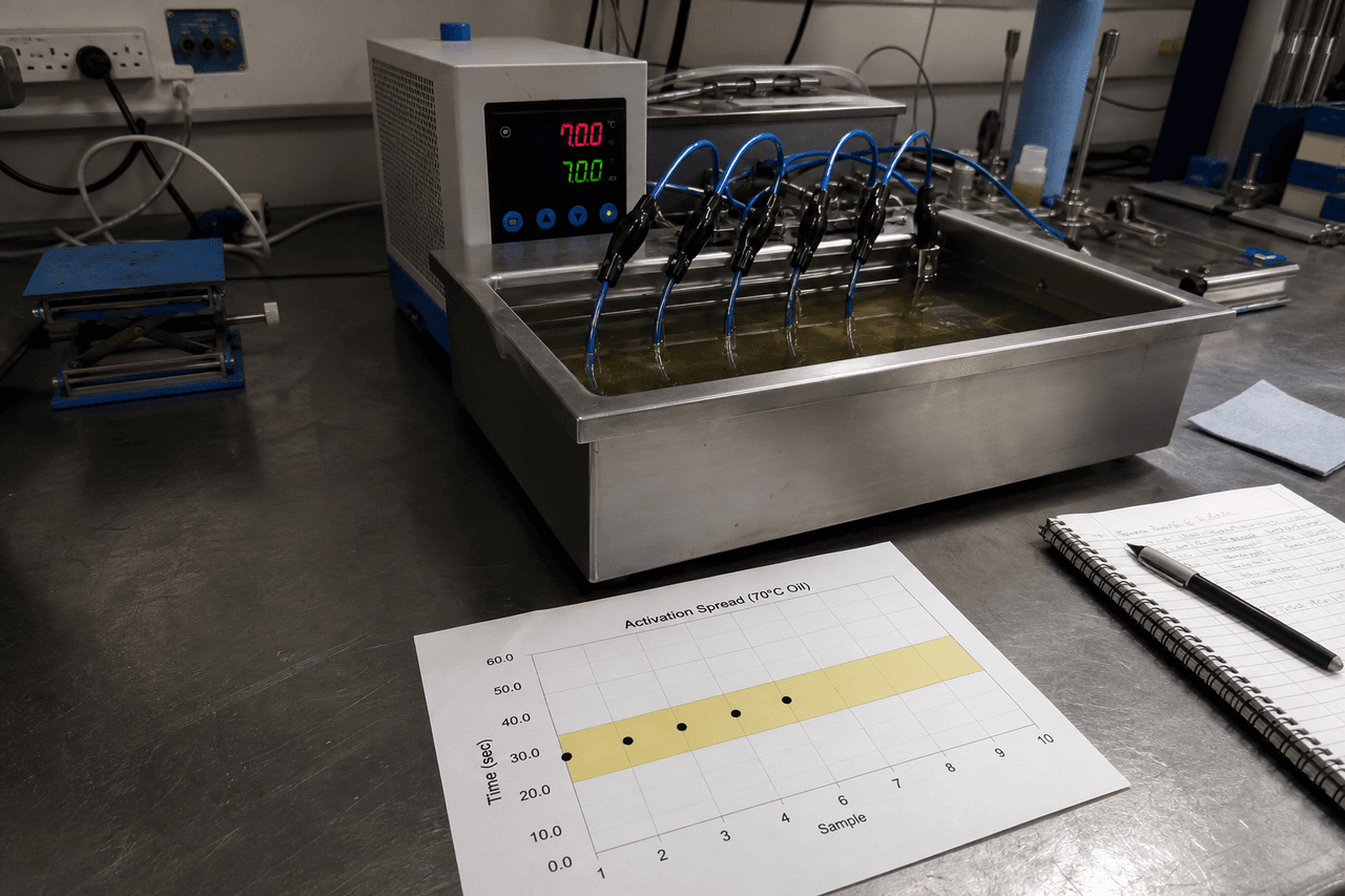
That distinction changes how the number should be read. A ±15 K band on an 88 °C class means the production spread of activation points should sit between roughly 73 and 103 °C; a ±5 K band on the same class means the same spread has to be squeezed into 83 to 93 °C. Tightening the band does not change the target — it demands a narrower distribution around it, which is a manufacturing problem before it is a paperwork problem. The bench method that measures this spread is the activation-point spread test: three one-metre samples per batch ramped slowly in a controlled-temperature oil bath, with the spread across them standing in for the spread across the run.
Production spread allowed across roughly 73–103 °C. The compound and process have room; the broadest supplier list can hold it.
Same spread squeezed into 83–93 °C. The compound batch and the bench acceptance window both have to be controlled to keep the distribution inside the band.
Reading the band as a distribution is what keeps the rest of the decision honest. A buyer who treats ±5 K as a label to add for safety, rather than as a narrower distribution someone has to manufacture and verify, is the buyer who is surprised by the quote and the lead time.
The Feasibility Ladder — ±15, ±10, ±5 and Below
How tight a band a programme can ask for is not a free choice along a smooth scale. It steps. Each step down asks more of the compound, the process and the QC bench, and narrows the list of factories that can hold it. The ladder below is the practical shape of the question how tight can the activation tolerance be for a make-to-order thermal sensor cable.
| Band | What it takes on the factory side | Supplier feasibility | Sample lead-time effect |
|---|---|---|---|
| ±15 K | The default for the standard six; in-process discipline alone usually holds it. | Broadest list; easiest to second-source. | Shortest; standard catalogue compound. |
| ±10 K | Disciplined process control plus compound batch consistency; tighter bench acceptance window. | Moderately narrower; many factories can hold it on request. | Modestly longer; usually no new compound. |
| ±5 K | Selected compound batches, a tight activation-spread acceptance window, and a sample-approval gate before the commercial run. | Narrower; not every factory holds it on every class. | Longer; compound selection and sample approval add steps. |
| Tighter than ±5 K | Rare as a two-sided band; usually handled with a one-sided band around a critical edge or a custom set-point shift. | Smallest; case-by-case engineering review. | Longest and least predictable. |
Two points matter more than the exact figures, which depend on the compound, the class and the individual factory. First, the achievable band is a function of where the class sits as well as how tight the number is — a tight band on a mid-range class is a different ask from the same band near the top of the make-to-order range. Second, the floor for most programmes is ±5 K as a two-sided specification; below that, the cleaner engineering answer is usually to stop tightening the band and either go one-sided or move the set-point, rather than to push a factory toward a distribution it cannot reliably reproduce batch after batch.
What Tightening Costs — Four Places the Price Shows Up
Tightening the band is never free, and the cost rarely lands as a single line on the quote. It shows up in four places, and a buyer who can see all four can decide whether the route or the host product actually needs to pay them.
Each step down removes factories that cannot hold the distribution on this class, which weakens second-source leverage on price and lead time.
A narrower acceptance window raises the share of production that falls outside the band and has to be re-graded or set aside, which feeds back into unit price.
Compound batch selection and a sample-approval gate add steps before the commercial run, so the first delivery is slower than a standard-band order.
A tight band makes batch-to-batch consistency harder to repeat, so the re-order carries more verification than a re-order on the default band.
The anti-pattern is paying all four with no route or product reason: the deployment sees none of it because the headroom was already generous, so tighter has to be something the application needs rather than something the spec sheet adds by default. The opposite anti-pattern is worse — leaving the band off the RFQ entirely, which lets the supplier quote against the loosest distribution their process happens to support.
Where a Tight Custom Tolerance Earns Its Place
A tight band pays for itself when a narrow window sits close to the trip point — and that is most common on the device side, where the cable is part of a host product's safety case rather than watching an open route. The reverse-lookup below maps five deployments to a starting band and the reason behind it; the band is a starting point for the route survey or the host-product spec, not a catalogue rule.
Starting band: tight (±5 K or one-sided). A verification window near 95 °C cannot absorb a ±15 K scatter, and the trip has to sit between the cell's normal peak and the runaway threshold. This is the case a tight band was made for. Yellow flag: a ±5 K band around an 88 °C class only reaches 93 °C — short of a 95 °C target — which usually points to a custom set-point rather than just a tighter band.
Starting band: ±10 to ±5 K. The cut-off has to trip before a defined component limit but not nuisance-trip in normal operation, so the corridor between the two is the binding constraint. The appliance safety OEM note covers why this cable sits in the cut-off path; the tolerance is how tightly that trip has to land. Yellow flag: a one-sided band is often cleaner than a symmetric one here.
Starting band: inherited from the host spec. The set-point and tolerance usually come from the equipment vendor's documentation, not the cable catalogue, so the band is a requirement to meet rather than a choice to optimise. Yellow flag: confirm the reference conditions match the equipment's qualification test before agreeing the band.
Starting band: ±15 K default. A tray, tunnel or warehouse run with comfortable headroom over the working ambient has a wide alarm-response window and gains little from a tight band — the supplier-list and QC cost buys nothing the deployment can see. Yellow flag: tighten only if the ambient peak sits close to the class.
Starting band: ±15 to ±10 K. Hot-aisle drift narrows the headroom on the 88 °C class, so a moderately tighter band can earn its place where the ambient peak runs close to the class. Yellow flag: a class step before a band tightening is often the cheaper move.
The pattern across the five is consistent: tighten where a narrow window sits close to the trip point, and stay on the default band where the headroom is wide. The sensor-type context for the device-side cases — whether a trigger element belongs in the loop at all — sits in the thermal sensor cable versus thermistor versus thermocouple note.
Two-Sided, One-Sided, and the Conditions a Band Is Meaningless Without
A tolerance number on its own is not a specification. Two things have to travel with it, or the band cannot be quoted against or verified.
The first is the shape of the band. A two-sided ±X K band treats overshoot and undershoot as equally undesirable, which suits a route where both nuisance-tripping and late tripping carry cost. A one-sided band — for example +0 / −10 K around a cut-off edge — says one direction is the binding constraint and the other has margin to spare. Cut-off applications often read better as one-sided: the trip must not happen above a hard ceiling, but tripping a little early is acceptable. Stating the shape removes the ambiguity a bare ± hides.
The second is the reference conditions the band is measured under. The same compound reads a different activation point at a faster bath ramp or on a shorter sample, so a band with no reference conditions is not verifiable. A clean spec pins three things: the sample length, the bath ramp rate (commonly around 1 K per minute), and any conditioning before the reading. Field 2 of the specification guide carries the class and band; the reference conditions are what make the band on Field 2 mean the same thing on the supplier's bench, the buyer's bench and the batch report.
Three Comparisons That Shape the Decision
A Tight Band on the Datasheet Is Not a Tight Band at Year Ten
One caveat sits underneath every tolerance decision: the band on the datasheet describes the cable as shipped, not the cable after years on the route. The activation point drifts in service — oxidation, thermal cycling fatigue, moisture ingress and dielectric aging each move it by a different mechanism and on a different timescale. A cable specified at ±5 K as-shipped does not stay inside ±5 K against its original target for its whole service life; the in-service distribution is wider than the as-shipped one.
That has a practical consequence for how tight a band is worth buying. Paying for ±5 K as-shipped on a route whose aging will widen the effective band well beyond that within a few years buys precision the deployment cannot keep. The aging mechanisms and their directions are walked through in the thermal sensor cable engineering reference; the selection takeaway is to match the as-shipped band to a window the route can still respect after aging, rather than to the tightest number the factory will quote.
How to Verify the Band Was Actually Held
A custom tolerance is only as real as the verification behind it, and the verification happens in three places that should agree with one another.
| Where it is checked | What confirms the band |
|---|---|
| Sample evaluation bench (pre-PO) | An offcut ramped in a controlled-temperature oil bath toward the rated point, under the reference conditions on the spec, shows whether the supplier can land inside the band before the order commits. |
| Outgoing batch inspection report | The measured activation value and the spread across the standard three samples per batch are read against the band agreed in the RFQ — not against a generic threshold. |
| Activation-point spread test (QC parameter 1) | The production-line method behind the report value; the spread it measures is the bound on the band the spec can promise batch after batch. |
An acceptance-sampling rule on incoming inspection closes the loop, so the band on the spec sheet, the band on the sample bench, the band on the batch report and the band the buyer re-checks on arrival are all the same band. A custom tolerance that is written but never verified at these stages is a number on a page, not a property of the cable.
The class says where the cable should trip; the tolerance says how tightly the production spread is allowed to scatter around it. Read the band as a distribution, tighten it only where a narrow window earns the cost, write it with its shape and reference conditions, and verify it on the bench and the report — so the tight number on the spec sheet is one the factory can hold and the route can keep.
FAQ — Custom Activation Tolerance
What does custom activation tolerance mean on a thermal sensor cable, and how is it different from the activation class?
The activation class is the target temperature — one of the standard six (68, 88, 105, 138, 170, 185 °C) or a custom set-point. The activation tolerance is the band around that target the cable is allowed to trip within, and on a thermal sensor cable it is better read as a production distribution rather than a per-metre promise. A factory does not make every metre activate at exactly the class; it makes a compound whose activation point falls inside a band, and the spread across samples is what the band has to contain. The standard six carry a default ±15 K band. A custom activation tolerance is a request to hold a narrower band — typically ±10 K or ±5 K — around a standard class or a custom set-point. So the class answers where the cable should trip; the tolerance answers how much the production spread is allowed to scatter around it. The two are specified on separate rows, and tightening the tolerance is a different decision, with a different cost, from moving the class.
How tight can the activation tolerance band realistically be — is ±5 K achievable?
±15 K is the broadest, lowest-cost default and the easiest to second-source. ±10 K is generally achievable with disciplined process control and compound batch consistency, on a moderately narrower supplier list. ±5 K is the practical floor for most make-to-order programmes — it tends to need selected compound batches, a tighter activation-spread acceptance window on the production bench, and a sample-approval gate before the commercial run, which together narrow the supplier list and lengthen the sample lead time. Bands tighter than ±5 K are rare as a two-sided specification; when a project genuinely needs them, the cleaner answers are usually a one-sided band around a critical edge or a shift to a custom set-point so the standard band lands where it is needed. None of these is a universal rule — the achievable band depends on the compound chemistry, the class, and the individual factory's process, which is exactly why the band belongs on the RFQ and the sample-approval gate rather than assumed from the catalogue.
When is a tight custom activation tolerance worth the cost?
A tight band earns its cost when a narrow verification or safety window sits close to the trip point, which is most common on the device side. An electric-vehicle battery pack whose thermal-runaway verification runs near 95 °C cannot absorb a ±15 K scatter; an appliance over-temperature cut-off that has to trip before a defined component limit but not nuisance-trip in normal operation has only a narrow corridor to land in; medical and laboratory equipment with a documented set-point inherits the host product's tolerance. By contrast, an open-route LHD fire-detection run with comfortable headroom over the working ambient usually has a wide alarm-response window and gains little from a tight band — the supplier-list and QC cost buys nothing the deployment can see. The test is whether the route or the host product has a window narrow enough that ±15 K would either nuisance-trip or trip too late. If it does, tightening earns its cost; if it does not, the default band plus the right class is the cheaper, more second-sourceable answer.
How do I write and verify a custom activation tolerance on the RFQ?
Write the class and the band on separate rows, state whether the band is two-sided (±X K) or one-sided (for example +0 / −10 K around a cut-off edge), and pin the reference conditions the band is measured under — the sample length, the bath ramp rate (commonly around 1 K per minute), and any conditioning before the reading. A band with no reference conditions is not verifiable, because a faster ramp or a different sample length moves the measured point. On the verification side, the band is confirmed in two places: the buyer-side sample evaluation bench before the PO, where an offcut is ramped in a controlled-temperature oil bath toward the rated point, and the outgoing batch inspection report, where the measured activation value and the production spread across the standard three samples per batch are read against the band agreed in the RFQ rather than against a generic threshold. An acceptance-sampling rule on incoming inspection closes the loop. The band is only as real as the reference conditions and the verification behind it.