When a thermal sensor cable alarms too early, fails a loop-resistance check, cracks at a gland or drifts out of panel tolerance years before its planned service life, the instinct is to blame the cable batch. In most failure reviews we run, the root cause sits earlier: the specification treated a safety cable like a commodity wire. The activation point was named, the route was assumed, and the atmosphere, jacket, termination and alarm margin were left for installation day.
Below are the five thermal sensor cable specification mistakes we see most often on LHD loops, thermosensitive appliance cables and heater-adjacent alarm paths — why each one shortens service life, and what to write instead. Heater examples remain useful because the same NiCr/FeCrAl alloys and atmosphere physics appear inside sensing cables, but the target here is cable reliability.
Mistake 1 — Choosing by Activation Point Alone
The quickest path to a wrong thermal sensor cable is to ask only for the activation temperature — 68 °C, 88 °C, 105 °C or 138 °C — and ignore where the cable lives. Activation point decides when the compound trips. It does not decide whether the jacket survives oil mist, whether the conductor drifts in chloride condensate, or whether the panel sees a stable loop after ten years.
- The cable route owns the activation budget. The route's worst legitimate temperature — summer ambient + enclosure soak + start-up overshoot — must sit at least 20–30 K below the activation point, or the loop will nuisance-trip before it ever sees a fault. The catalog activation point is a ceiling, not a target.
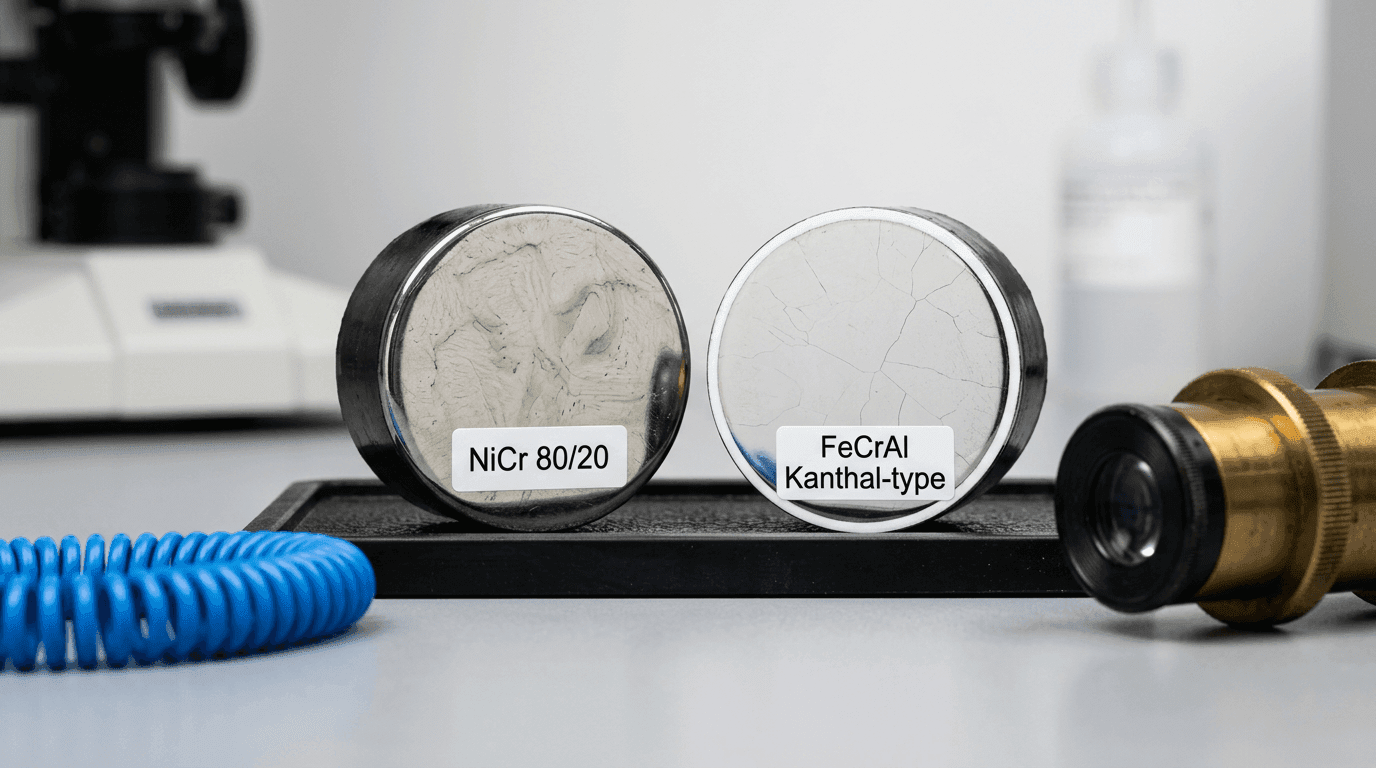
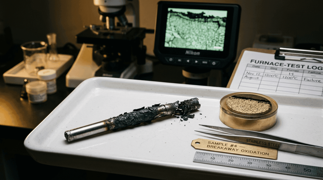
- The atmosphere owns the conductor decision. Chloride condensate from coastal air, sulfur traces from combustion plants, ammonia from refrigeration leaks — any of these will drift the conductor's resistance baseline through the jacket over years and corrupt the alarm signal long before the activation compound is challenged. Pick NiCr for clean dry routes, jacketed FeCrAl-cored cable for sulfur-bearing or saline plants, and confirm against our NiCr vs Kanthal conductor decision matrix.
- The jacket owns ten-year reliability. Oil mist, solvent vapour, UV exposure, abrasion and mechanical flex all degrade the jacket before the compound is touched. Activation point alone tells you nothing about whether the cable will still be a cable in year five — that is decided by jacket chemistry against the route audit.
Fix. Document the cable route first — worst-case ambient, atmosphere, mechanical path, panel input and maintenance access — then choose activation point, jacket and conductor together. The activation number is the last decision in the sequence, not the first.
Mistake 2 — Treating Jacket Material as a Colour Choice
The jacket is the cable's environmental system, not the coloured skin. It decides smoke toxicity, chemical resistance, UV life, oil-mist survival, flex behaviour, waterproofing and thermal response time. Two cables with the same conductor and activation compound can live very different lives if one is PVC in a coastal tunnel and the other is fluoropolymer in the same route.
Indicative jacket picks by route:
Fix. Specify jacket material against route conditions — ambient heat, chemicals, smoke code, flex, UV and water ingress — before negotiating colour, print legend or spool format.
Mistake 3 — Routing Without Alarm Margin
A cable route that looks reasonable on a layout drawing can still live too close to a normal heat source. The cable then sees repeated legitimate temperature peaks and the panel receives nuisance alarms. The opposite mistake is just as common: routing the cable so far from the hazard that the protected asset reaches damage temperature before the compound does.
The signature is unmistakable. The same loop alarms during every start-up, every hot production run or every summer afternoon, while inspections show no fire and no local damage. On the other side, a motor winding or heater bracket shows heat damage but the cable stayed just cool enough to miss the event.
Fix. Measure the actual cable-route temperature under worst normal conditions, then specify the activation point and standoff around that number. For heater-adjacent routes, run a short commissioning soak with the cable clipped exactly where it will live; paper calculations are not enough.
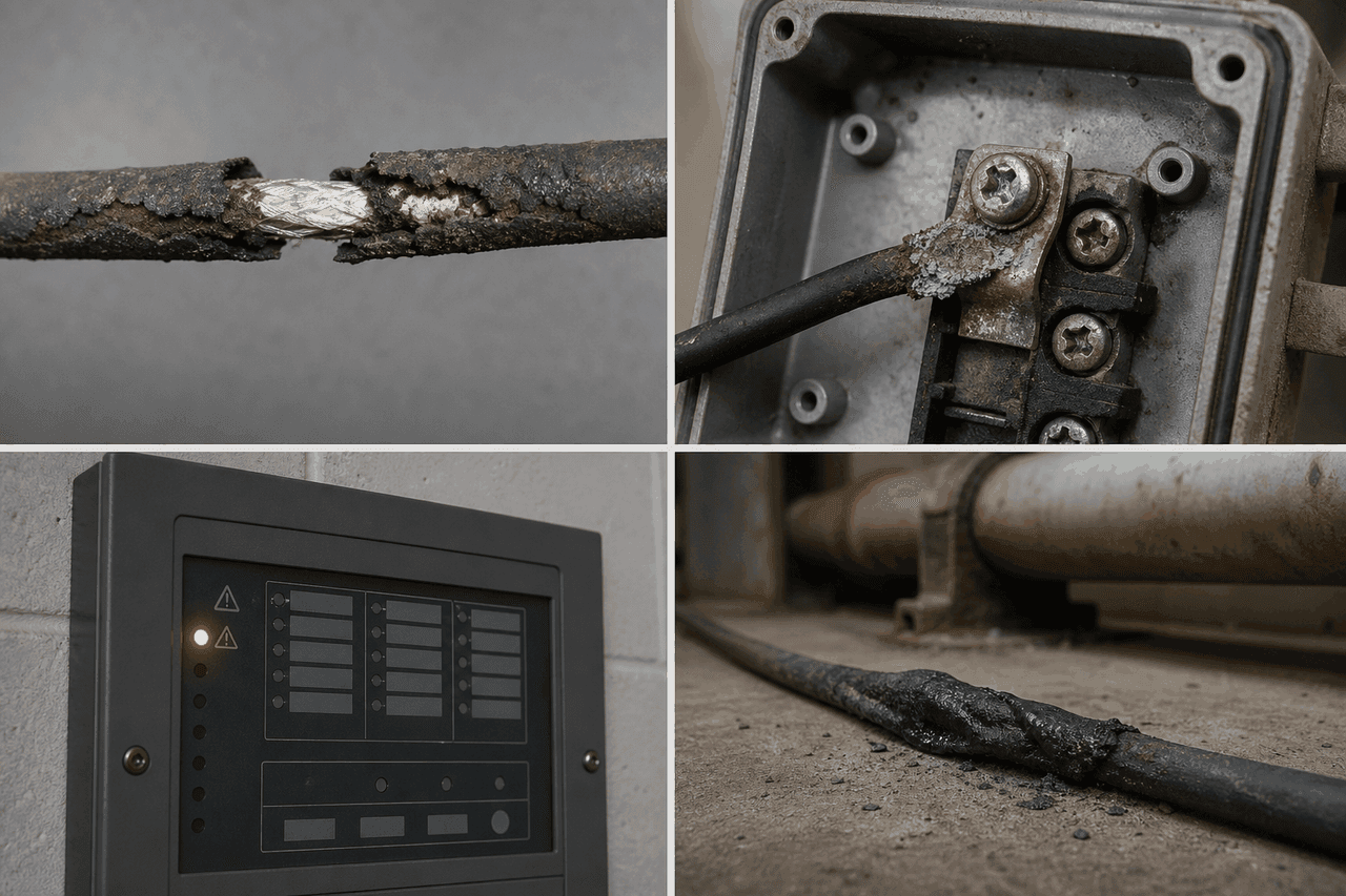
Mistake 4 — Neglecting the Gland and Terminal Zone
Ask a commissioning engineer where LHD and thermosensitive cable faults actually start and the answer is rarely the middle of a clean straight run. It is at the gland, splice, end-of-line resistor, panel entry or bend where the installer had too little room. That zone combines water paths, compression, strain and electrical termination in one place.
Three recurring design errors explain most termination failures:
- Wrong gland for the jacket. A hard compression gland can cut soft silicone; an undersized gland can ovalise the jacket and create a capillary path for moisture.
- Exposed EOLR or splice. A resistor or splice that sits in condensate becomes the loop fault, not the detection cable.
- No strain relief at panel entry. A tight bend or unsupported drop works the conductor and jacket every time the cabinet door or tray vibrates.
Fix. Treat the termination as part of the cable specification: compatible gland, drip loop, bend-radius callout, sealed EOLR enclosure, labelled lot number and inspection access.
Mistake 5 — Specifying With Zero Alarm Margin
The activation temperature on a thermal cable datasheet is the trip point, not the operating temperature. If the normal cable route reaches that number during hot weather, cleaning cycles or enclosure soak, the loop will nuisance-alarm; if the activation point sits too high above the protected asset's damage threshold, the cable will alarm too late.
- Measure the highest normal temperature at the cable route, not at the heater or motor core.
- Include enclosure soak, summer ambient, blocked ventilation and start-up overshoot in the normal envelope.
- Reserve the activation point for faults that actually require alarm or cut-off.
Rule of thumb: keep 20–30 °C between the highest legitimate cable-route temperature and the activation point, then tighten or widen that margin only with measured data.
The same logic applies to two other axes. Atmosphere margin — design against the worst case the plant can produce, not the typical case — matters because corrosion and jacket failures cluster around process upsets. Duty-cycle margin — cyclic heat beside the cable is harder than steady ambient because the route repeatedly crosses the edge of the alarm envelope. For heater-adjacent routes, see our note on thermal sensor cable near cyclic-duty heaters.
Fix. Add margin on all three axes — temperature, atmosphere, duty cycle — before the specification is released. A slightly better jacket, a tighter activation band and a better termination are orders of magnitude cheaper than a false alarm or a missed over-temperature event.
A Seven-Item Pre-Release Cable Checklist
Before any thermal sensor cable specification leaves our engineering desk, the following seven items have to sign off. Every item is a line drawn around one of the five mistakes above.
- Application mapped to platform — LHD fire-panel loop or TS in-equipment cut-off.
- Highest normal cable-route temperature measured, not guessed.
- Activation point selected with a documented alarm margin.
- Jacket material matched to atmosphere, smoke code, water ingress and flex.
- Gland and termination method specified, including EOLR protection.
- Route geometry audited — bend radius, abrasion points, supports and heat shadows.
- Batch report required — activation, insulation resistance, waterproof, tensile and burn-speed checks.
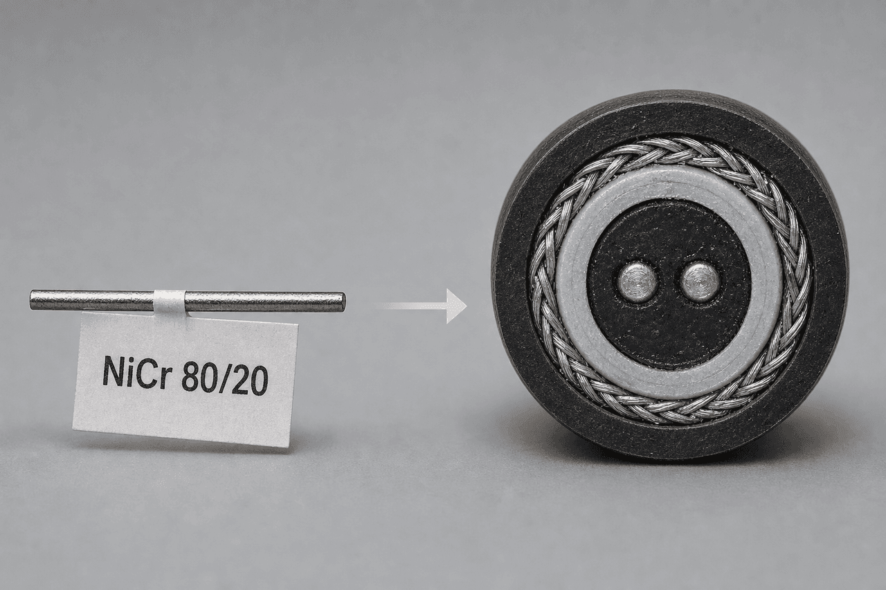
How These Mistakes Trace Back to the Conductor Inside the Cable
Four of the five mistakes above touch the cable's conductor — the NiCr or FeCrAl wire that runs the length of every thermal sensor cable and linear heat detection loop. The conductor sits at ambient 99% of the time, but its long-term resistance is what the panel reads as "the loop is healthy". Chloride or moisture creeping past a degraded jacket attacks that conductor slowly; a poor termination joins it badly; an out-of-margin route ages it under cyclic stress. For the alloy decision behind the conductor itself — when NiCr is right, when FeCrAl earns its place, what the temperature and atmosphere envelope demand — see our conductor alloy framework for thermal sensor cables. If you are sourcing the finished sensing cable rather than bare wire, the cable platforms — LHD Series for fire panels and TS Series for OEM equipment — are listed on our products page.
How We Help
Our engineering team specifies LHD and thermosensitive cable for chemical, mining, appliance, battery, motor and heater-adjacent projects. If you want an outside read on a live specification — or a clean-sheet recommendation for a new route — send us the cable path, highest normal route temperature, atmosphere, panel topology and target service life. We will return a platform choice, jacket call-out, conductor recommendation and batch-test package against your specification.
FAQ — Specification Mistakes That Shorten Cable Life
Is activation temperature alone enough to choose a thermal sensor cable?
No. Activation temperature is only one line in the specification. The cable route, jacket chemistry, ambient temperature, atmosphere, panel topology, bend radius, gland sealing and alarm margin decide whether the cable survives and alarms correctly. Two 105 °C cables can behave very differently if one is routed beside oil mist and the other in a clean indoor cable tray.
What is the most common jacket mistake on LHD and TS cables?
The most common mistake is using the cheapest standard jacket where the route actually needs LSZH, silicone or fluoropolymer. PVC may be fine in a clean indoor tray, but tunnels need LSZH for smoke toxicity, motor and heater-adjacent routes need silicone for ambient heat, and chemical or oil-mist environments need fluoropolymer. Jacket mismatch is the fastest path to drift, cracking or nuisance alarms.
Why do thermal sensor cable failures often start at terminations?
Terminations combine moisture paths, mechanical strain, gland compression, end-of-line resistor wiring and panel-side workmanship. A perfect cable can still show false short, open circuit or resistance drift if the termination leaks, the gland cuts the jacket, the EOLR is exposed to condensate or the cable is bent too tightly at the panel entry.
How much alarm margin should a thermal sensor cable specification include?
A useful starting point is 20–30 °C between the highest legitimate cable-route temperature and the cable's activation point. Tight industrial or appliance designs can use a smaller engineered margin if the route is thermally isolated and measured. Never choose the activation point from the protected asset's damage temperature alone; measure the cable route, then set the margin.