A new LHD loop is wired, the resistor is on the far end, the cable is clipped along the tray, and the panel is energised for the first time — and zone three immediately throws a fault. Nobody touched the cable. The activation point is fine. The fault is arithmetic: the resistor on the end did not match the value the zone card was built around, or the run was long enough that the cable's own resistance pushed the loop out of the window the panel reads as healthy. The panel never sees a cable. It sees a number, and the number was wrong before anything got hot.
This note is about that number — how a panel supervises an LHD cable by reading the resistance of a series loop, where the end-of-line resistor value comes from, how much resistance the cable itself adds over a run, and how to keep the sum inside the panel's window before power-on. It does not re-cover where the cable sits on a panel drawing or the four supervisory states the loop reports — that is the subject of the panel wiring and commissioning note — nor does it diagnose a loop that has already faulted in service, which is the job of the field-diagnosis sequence. Here the focus is narrower and earlier: the calculation a specifying or commissioning engineer does so the loop reads clean the first time it is switched on.
What the Panel Actually Measures
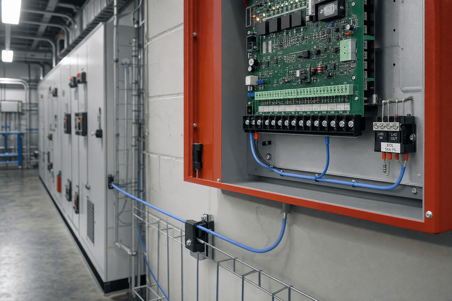
A conventional fire-alarm panel does not know whether an LHD cable is intact, broken or alarming. It only measures one thing continuously: the resistance of the loop wired to a zone card. The two inner conductors run out to the far end of the protected run, where an end-of-line resistor bridges them, and the panel pushes a small supervisory current — commonly at around 24 VDC — through that series circuit and watches the resistance it implies.
Three resistances sit in series in that loop, and the panel reads their sum:
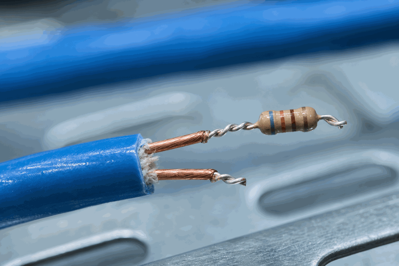
A fixed resistor across the far-end conductors. It is the dominant term and the reference the panel's window is built around — usually a kilo-ohm-scale value chosen by the panel manufacturer.
The resistance of the two conductors carrying current out to the far end and back. It scales with run length and with the conductor's resistance per metre — small on short runs, far from negligible on long ones.
Every lug, splice and connector adds a little resistance. Tight and clean it is negligible; loose or corroded it grows over the years and shows up as a slow climb in the loop total.
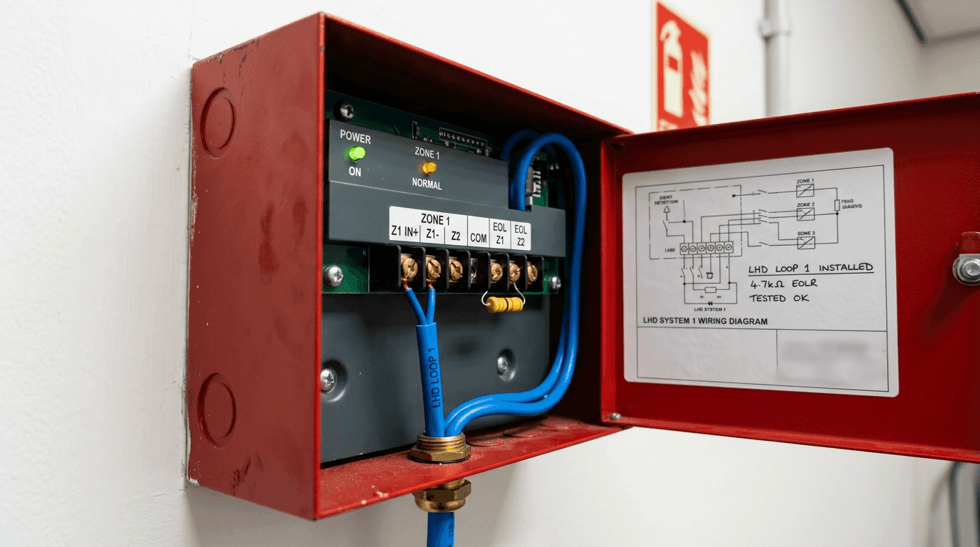
From those three the panel infers state. With the resistor in circuit and the conductors intact, the loop sits in the normal band and a supervisory current flows. When the cable activates, the two conductors short together at the hot point, the resistance collapses far below the EOL value, current jumps, and the panel reads alarm. If a conductor breaks or the resistor falls off, current stops and the loop reads open fault. The whole scheme works only if the resistance of a healthy, quiet loop is unambiguously inside the normal band — which is exactly what the calculation checks.
The EOL Resistor Value Is the Panel's Number, Not Yours
The most common first mistake is treating the end-of-line resistor as a free engineering choice. It is not. The supervision circuit on the zone card is designed around one specific resistance, and the resistor on the far end has to be that value. Different panel families settle on different figures, and the only correct value for a given install is the one in that panel's documentation.
| What sets the EOL value | What it means for the loop |
|---|---|
| The panel zone card | The card's supervision electronics define the expected resistance. Common conventional values land at 2.2 kΩ, 3.9 kΩ, 4.7 kΩ, 6.8 kΩ or 10 kΩ — but the figure is read from the panel manual, not assumed. |
| Wrong value fitted | Too high and the loop reads as an open or near-open fault; too low and it reads toward the alarm edge. Either way the zone faults at power-on with a perfectly good cable on it. |
| Addressable panels | A dry-contact LHD zone is interfaced through a monitor module that carries its own supervised input and its own end-of-line device — the resistor matches the module, not the main loop. |
| Resistor placement | The resistor belongs at the electrical far end of the run, after the last metre of cable — not in the panel cabinet. A resistor wired at the panel end supervises the wiring to the cabinet and nothing of the cable run. |
So the engineering question is never “what resistor should I pick?” It is “the panel calls for this value — does the rest of the loop still land in the window once the cable is added?” That is where the cable's own resistance enters. Matching the panel's required value and window to the cable is one of the four lines of the wider panel-compatibility check a buyer settles before the order.
The Resistance the Cable Adds Over the Run
Each conductor in the cable has a resistance per metre, quoted on a complete spec sheet in ohms per metre or ohms per kilometre. Because the supervisory current runs out along one conductor and back along the other, the conductor contribution to the loop is roughly:
R(cable loop) = 2 × run length (m) × conductor resistance (Ω/m)
The factor of two is the part people forget — a 300 m run is 600 m of conductor in the supervised path. How much that matters depends entirely on the conductor:
| Conductor type | Loop resistance behaviour |
|---|---|
| Low-resistance copper-based pair | A fraction of an ohm per metre per conductor. Even a long run stays in the tens of ohms — negligible next to a kilo-ohm EOL resistor. |
| Higher-resistance sensing conductors | Some thermal sensor cable architectures use thin or alloy conductors with markedly higher resistance per metre. Over hundreds of metres the loop can reach hundreds of ohms and becomes a real fraction of the panel's window. The cross-section behind that difference is the subject of the metal-core versus non-metal-core architecture note. |
| Aged terminations on top | Independent of conductor type, every degraded joint adds series resistance that stacks onto the conductor loop and pushes the total the same direction — up. |
This is why a cable's conductor resistance per metre is not a trivia field on the data sheet. On a short copper-pair run you can ignore it; on a long run, or a sensing architecture with resistive conductors, it is the term that decides whether the loop still reads clean — and it is precisely the figure a supplier should be able to state, alongside the activation class and jacket, as one of the rows of a complete specification sheet.
A Worked Calculation
Take a concrete case. A conventional zone card calls for a 4.7 kΩ end-of-line resistor and supervises at roughly 24 VDC. The run is 400 m of cable whose conductor resistance is about 0.2 Ω/m per conductor, and the terminations add a couple of ohms. The cold loop resistance the panel will see is:
EOL resistor          =  4 700 Ω
Cable loop            =  2 × 400 m × 0.2 Ω/m   =  160 Ω
Terminations          =  ~2 Ω
-------------------------------------------------
Cold loop total       ≈  4 862 Ω

Supervisory current   =  24 V / 4 862 Ω          ≈  4.9 mA
The cable has added about 160 Ω — roughly 3% on top of the 4.7 kΩ reference. Whether that is comfortable depends on how wide the panel's normal band is around its nominal EOL value; a card that accepts, say, the EOL value plus or minus a few hundred ohms swallows this easily, while a tight window or a much longer run would not. Change one input — double the length to 800 m, or swap to a conductor at 1.0 Ω/m — and the cable loop jumps to 320 Ω or 800 Ω, and the second of those is no longer a rounding error against 4 700 Ω. The supervisory-current line above is a simple Ohm's-law approximation; the acceptance limit still comes from the panel or monitor module's stated normal window. The calculation is simple; the discipline is doing it with the real conductor figure and the real run length before the resistor is ever fitted, rather than discovering the margin on power-on day.
The check, in one line: required EOL value + (2 × length × Ω/m) + terminations should land inside the panel's normal supervision band. If it does not, the answer is rarely a different resistor — it is a shorter zone, a lower-resistance conductor, or splitting the run.
Multi-Zone, Series and Parallel
When the loop total will not fit a single zone — because the run is too long, the conductor too resistive, or the project needs to locate an alarm to a shorter section — the run is split into zones. Each zone is its own out-and-back loop with its own end-of-line resistor on its own zone card. That serves two purposes at once: it shortens the supervised length so an alarm is located to a section rather than the whole building, and it keeps each loop's resistance comfortably inside the window.
Two wiring rules follow, and both come straight from the fact that the panel reads a single series resistance per loop:
- End-of-line resistors are not daisy-chained. One supervised loop has exactly one resistor, at its far end. Stacking resistors in series on one card or scattering them mid-run corrupts the resistance the card is built to read.
- LHD loops are not paralleled onto one card. Two cable runs across a single zone input put two resistances in parallel and a single short anywhere reads as alarm with no way to tell which run it came from — and the cold resistance no longer matches any clean calculation.
The other choice is the wiring class. Class B is the common out-and-back loop with the resistor at the end; a single break anywhere loses supervision of everything downstream of the break. Class A returns the loop back to the panel so the run is fed from both ends, and a single break still leaves both sides supervised — at the cost of more cable and a return path. The choice between them is a survivability decision driven by the code and the asset, sitting downstream of the architecture comparison in the linear heat detection architectures note; the resistance arithmetic above applies to each supervised segment either way.
Verifying the Maths at Commissioning
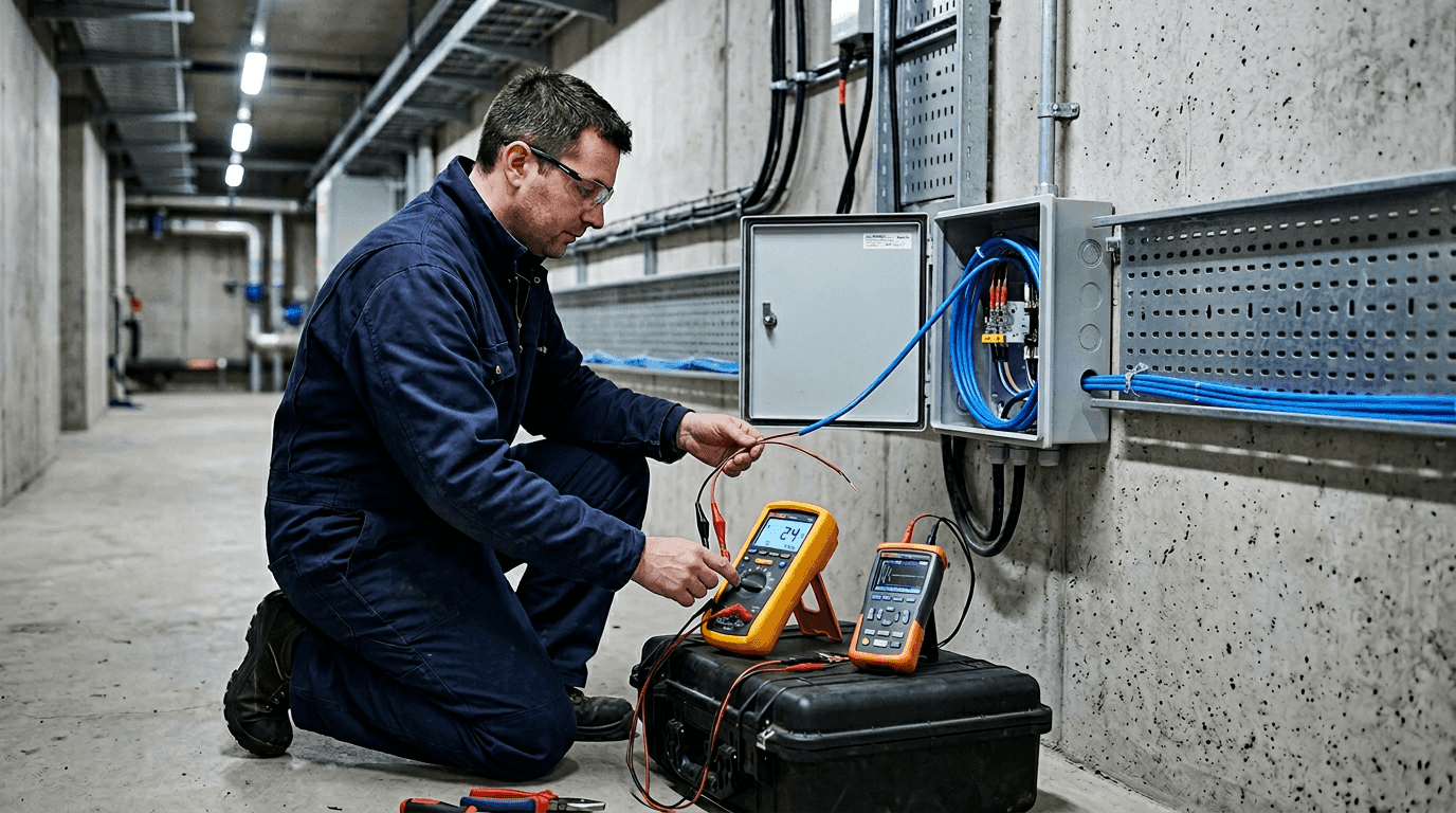
The calculation earns its keep at handover, when it turns into a measurement anyone can defend — one of the de-energised steps in the wider commissioning acceptance procedure that signs a loop over. With the loop disconnected from the panel, measure the resistance end to end across the two conductors with the end-of-line resistor in place, and compare the reading to the calculated total.
The EOL value is correct, the conductors are intact, and the terminations are clean. This is the number to record as the commissioning baseline.
Added series resistance — a loose or corroded termination, a partial conductor break, or a missing or wrong (too high) resistor. The panel will read this as an open or out-of-window fault.
A partial short along the run, or a smaller-than-specified resistor fitted by mistake. The panel reads this toward the alarm edge.
Recording that measured cold loop value against the calculation does two things: it confirms the loop is healthy on day one, and it gives a baseline a later reading can be measured against rather than guessed. A loop that has drifted a few hundred ohms over two years has a termination going bad; a loop that has dropped is wetting or crushing somewhere. Separating those once the system is live — a real activation versus a wet joint versus a crush fault — is the next reference point, the field-diagnosis sequence that adds insulation resistance and distance-to-fault checks to the loop reading. The point of getting the EOL and loop arithmetic right at the start is that the first of those calls is a clean baseline, not a mystery.
Conductor resistance: state Ω/m (or Ω/km) per conductor for the supplied construction.
End-of-line resistor: confirm the value required by panel model [____] and that it ships with the loop.
Loop check: cold loop resistance to be calculated as EOL + (2 × run length × Ω/m) + terminations,
and recorded by measurement at commissioning as the supervision baseline.
The panel never trusts the cable; it trusts a resistance. The end-of-line resistor is the number the panel was built around, the cable's conductors add a length-dependent term on top of it, and a good install is one where the sum was calculated with the real ohms-per-metre and the real run length before the resistor was fitted — then confirmed with a meter, not discovered when the zone faulted at power-on.
FAQ — LHD End-of-Line Resistor and Loop Resistance
Do you calculate the EOL resistor value, or does the panel specify it?
In most conventional fire-alarm installations you do not calculate the end-of-line resistor value at all — the panel's zone card dictates it. The supervision circuit on the card is designed around a specific resistance (commonly a value such as 2.2 kΩ, 3.9 kΩ, 4.7 kΩ, 6.8 kΩ or 10 kΩ depending on the manufacturer), and the resistor at the far end of the LHD loop has to match that figure. Fit a value the card does not expect and the panel reports an open or short fault the moment it is powered on. What you do calculate is whether the total cold loop resistance — the panel's required EOL value plus the resistance the cable conductors add over the run plus the termination resistance — lands inside the window the panel treats as normal. The EOL value is the panel's number; the loop total is the number you are responsible for keeping in range.
What is the loop resistance of a thermal sensor cable and why does it matter?
Loop resistance is the resistance the panel sees through the two conductors running out to the far end and back, before the end-of-line resistor is added. It equals roughly twice the run length multiplied by the conductor resistance per metre, because the supervisory current travels out along one conductor and back along the other. On a short run with low-resistance conductors it is a few ohms and disappears next to a kilo-ohm EOL resistor. It matters on long runs and on cables whose sensing architecture uses higher-resistance conductors, where the loop resistance can climb into the hundreds of ohms and start to eat measurably into the panel's supervision window. Added to corroded or loose terminations, it can push the cold loop total toward the edge of the normal band — which is why the conductor resistance per metre belongs on the spec sheet and in the loop calculation, not left as an assumption.
Can one fire panel zone supervise a very long LHD cable run?
A single supervised zone has a maximum run length, and it is set by two limits at once: the location granularity the project needs and the resistance window the panel can read. Past a certain length the cable's own loop resistance plus terminations drifts the cold reading out of the normal band, and a single break anywhere on a Class B loop loses everything downstream of it. Long routes are split into multiple zones — each its own out-and-back loop with its own end-of-line resistor on its own zone card — both to locate an alarm to a shorter section and to keep each loop's resistance inside the panel's window. Multiple end-of-line resistors are not daisy-chained on one card, and LHD loops are not paralleled to share a card, because either move corrupts the resistance the panel reads. Where survivability matters, Class A wiring returns the loop to the panel so a single break still leaves both ends supervised.
How do you verify the EOL resistor and loop resistance at commissioning?
With the loop disconnected from the panel, measure the resistance end to end across the two conductors with the end-of-line resistor in place. A healthy reading sits close to the calculated total — the panel's required EOL value plus roughly twice the run length times the conductor resistance per metre. A reading well above the calculation points to added resistance: a loose or corroded termination, a partial conductor break, or a missing or wrong-value resistor, which the panel will read as an open or out-of-window fault. A reading well below points to a partial short along the run or a smaller-than-specified resistor. Recording that measured cold loop value against the calculation at commissioning gives a baseline a later drift can be compared to. Separating a genuine activation from a wet or crushed loop once the system is live is a different exercise, covered by the field-diagnosis sequence using loop resistance, insulation resistance and distance-to-fault checks.