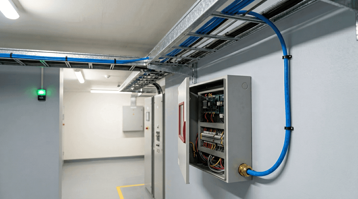
The cable is clipped along the tray, every splice is in an approved kit, the end-of-line resistor is on the far end, the panel is powered, and zone three sits quietly in the normal band. The installer calls it done. It is not done. A fire-detection zone is not finished when it is wired and quiet — it is finished when someone has driven it through a defined set of tests, watched it behave correctly for each one, written the results down and signed them against the project specification. The gap between “wired and quiet” and “accepted” is the commissioning acceptance procedure, and it is where a lot of otherwise good installations stall.
This note walks that procedure: what is confirmed cold before the loop is energised, what is tested live once it is, why the installed cable is generally not heated to activation, and what ends up on the acceptance record. It does not re-cover where the cable sits on the panel drawing or the four supervisory states the loop reports — that is the panel wiring note — nor the cold loop arithmetic itself, which is the end-of-line resistor and loop resistance calculation, nor how to diagnose a loop that faults later in service, which is the field-diagnosis sequence. Here the focus is the witnessed handover that sits between install and service.
Wired, Energised, Accepted — Three Different Milestones
It helps to separate three things that get casually treated as one. A loop is wired when the cable is mechanically installed, terminated and connected. It is energised when the panel is powered and the loop reads inside the normal supervisory band. It is accepted only when a defined test sequence has been demonstrated, recorded and signed against the specification, then handed to the authority having jurisdiction.
The trap is assuming the second milestone implies the third. A loop can be energised and sitting comfortably in the normal band and still fail acceptance, because a quiet normal reading proves only one of the states the panel has to recognise. Acceptance proves the loop also annunciates an open fault when a conductor is broken, an alarm when the cable activates, a ground fault where the panel supervises one, and that it returns to normal on reset. Quiet is necessary; it is not sufficient.
Before Power-On — The De-Energised Checks
The procedure starts with the loop disconnected from the panel, because the cleanest way to confirm the cable is whole is to measure it without the panel's supervision in the way. Four things are confirmed before anything is energised.
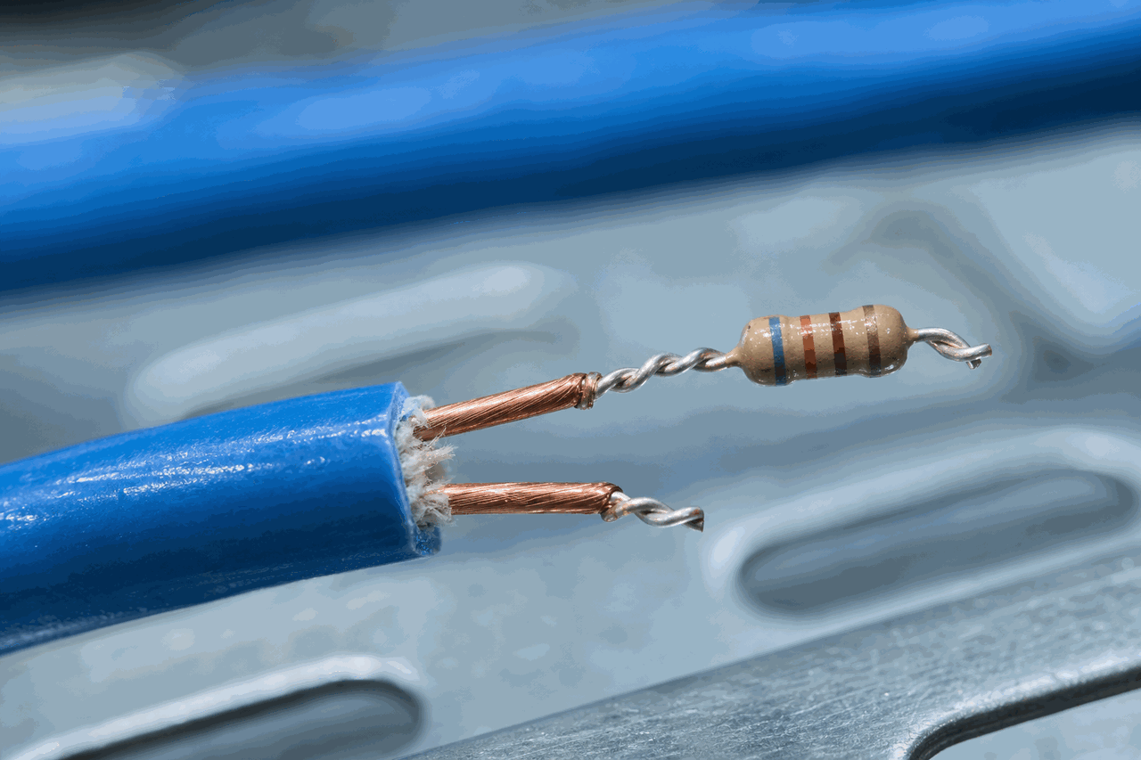
The run sits close to the ceiling or thermal-risk surface it is meant to watch, bend radii are respected, the cable is secured at the specified spacing, every splice is in a manufacturer-approved kit rather than a soldered joint, and the end-of-line resistor is at the electrical far end of the run — not in the panel cabinet, where it would supervise the wiring and none of the cable.
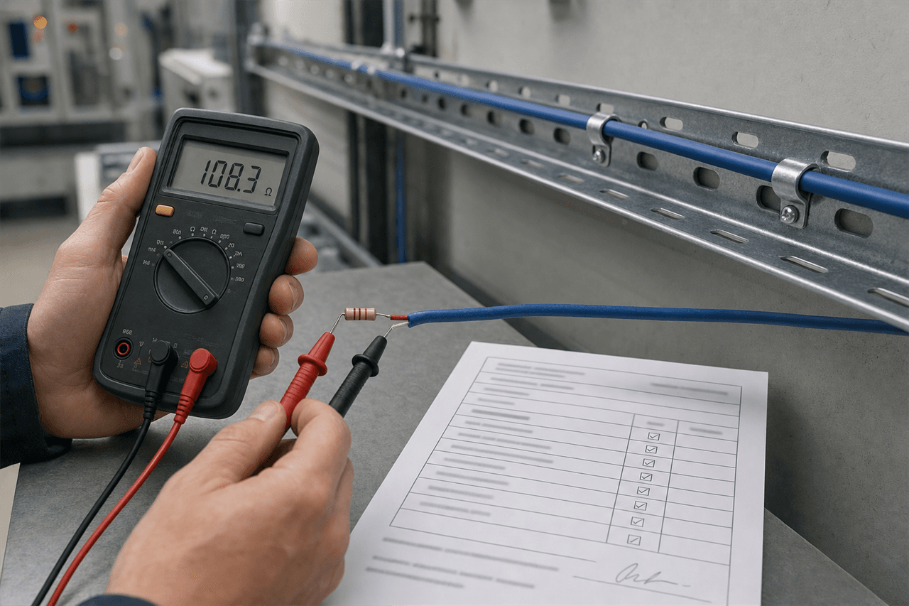
Measured end to end across the two conductors with the resistor in place, the reading should land close to the calculated total — the end-of-line value plus roughly twice the run length times the conductor resistance per metre plus the terminations. The arithmetic behind that figure is the subject of the loop resistance calculation; at acceptance it stops being a calculation and becomes a measurement that either matches or does not.
A megohmmeter reads the conductors against earth or screen, commonly looking for a minimum around 20 megohms with the actual number recorded rather than a bare pass tick. A low reading on a brand-new install points at moisture or mechanical damage at a joint, which traces back to how the IP rating is specified across the cable, the termination and the install, since water enters at the joints rather than through the jacket.
The resistor fitted at the far end is confirmed to be the value the panel's zone card calls for. A wrong value is the most common reason a perfectly good loop faults the instant it is energised, so it is checked against the panel documentation before power is applied, not after the zone throws a fault.
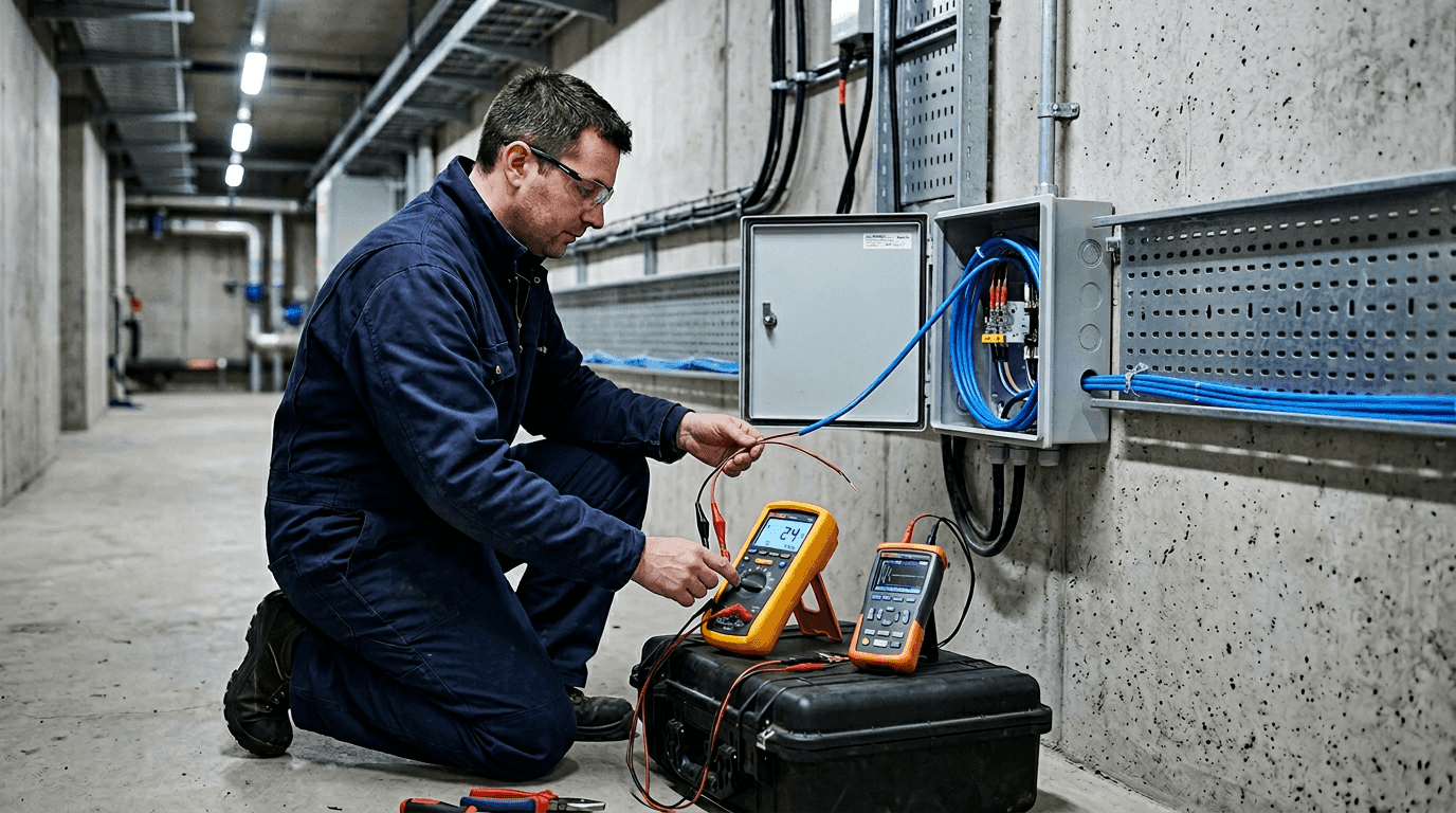
At Power-On — The Functional Tests
With the de-energised checks recorded, the loop is reconnected and the panel is energised. It should settle into the normal band. From there the procedure deliberately drives the loop through each condition the panel is supposed to recognise, and confirms the right annunciation each time:
- Supervisory normal. The loop reads normal with the resistor in circuit and a supervisory current flowing — the baseline state the rest of the tests deviate from.
- Induced open fault. Lift the end-of-line resistor or break the loop at the far end; the panel should annunciate an open fault. Restore it; the fault should clear. This proves the panel sees a broken conductor or a dropped termination as a supervised fault, not as silence.
- Alarm verification. Confirm the panel reads an alarm and reports it to the correct zone — done without sacrificing the live run, as the next section explains.
- Ground fault. Where the panel supervises a path to earth, that condition is induced and confirmed to annunciate as a ground fault distinct from an open or an alarm.
- Zone and address mapping. On an addressable system the monitor module is confirmed to report the right zone label to the operator graphic, so an alarm points to the right part of the building.
- Reset and restore. The system is returned to normal and the event is confirmed in the panel log, closing the sequence cleanly rather than leaving a latched state behind.
Why You Usually Do Not Heat the Installed Run
The instinct at acceptance is to heat the cable and watch the panel go into alarm. For the most common LHD construction that is the wrong move. A fusible, fixed-temperature cable activates by melting its heat-sensitive insulation so the two conductors short together, and that is a one-shot event — heating the deployed run to its activation point destroys that section and means cutting it out and re-terminating. The architecture decides what is reversible: the difference between a fusible core and a recoverable analog one is the metal-core versus non-metal-core architecture, and whether a cable is one-shot or resettable is exactly this question.
So the alarm path is normally proven two ways that leave the run intact. A documented short across the conductors at the end-of-line terminals confirms the panel reads a short as an alarm and annunciates the correct zone — it tests the panel and the loop, not the cable chemistry. A calibrated point-heat test on a short sacrificial offcut or a designated test section confirms the cable itself triggers inside its expected response window. An analog, resettable cable that recovers after heating can be point-heat tested on the installed run — following the panel manufacturer's commissioning procedure and keeping the heat source within the cable's rated limits — because nothing is consumed; a fusible one cannot. Matching the test method to the installed architecture is the difference between proving the system works and quietly damaging it during its own acceptance.
What Gets Recorded and Signed
None of the work above counts until it becomes a record. The acceptance procedure produces a commissioning certificate, and the value of that document is that it is specific: it captures numbers and named results, not a single “tested OK” line. A workable acceptance record carries the readings and outcomes from each step in one place.
Zone / loop ID and as-built run length
Cold loop resistance: measured ______ Ω  vs calculated ______ Ω
Insulation resistance to earth: measured ______ MΩ  (min spec ______ MΩ)
End-of-line resistor: value required ______  /  value fitted ______
Functional tests: normal [ ]  open fault [ ]  alarm [ ]  ground fault [ ]  reset [ ]
Alarm method: documented short at EOL [ ]  /  point-heat on test section [ ]
Observed response time on heat test: ______ s
Zone / address mapping confirmed to operator graphic: [ ]
Cable lot number ______  traced to batch inspection report: [ ]
Instruments used (with calibration dates) ______
Commissioning engineer ______   Witness ______   Date ______
Two of those rows do more than prove day-one health. The measured cold loop resistance and the insulation-to-earth reading are the baseline a later drift is measured against: a loop that has climbed a few hundred ohms over two years has a termination going bad, and one whose insulation has fallen is wetting somewhere. Recording them at acceptance is what makes the first field-diagnosis call a comparison against a known starting point rather than a guess. The lot-number traceability does the same for the cable itself, tying the installed run back to the batch inspection report that left the factory with it.
Who Witnesses, Who Signs, and What the Supplier Provides
The acceptance test is run by the installing fire-protection integrator, following the panel manufacturer's commissioning instructions and the local fire code, and it is witnessed by the authority having jurisdiction or the client's representative before the result is signed against the project specification. That ownership matters, and it draws a clean line around what a cable supplier can and cannot do.
The supplier does not perform or sign the on-site acceptance test — that responsibility sits with the integrator and the authority having jurisdiction. What a supplier can do is provide the data that lets the procedure go cleanly: the conductor resistance per metre that the cold loop calculation needs, the per-batch inspection report that backs the lot-number traceability, the activation class and tolerance that set the expected response window, and a compliance statement for the supplied model. Each of those is assessed on site by the people running the test, not taken as a sign-off in itself. Confirming that the cable matches the panel before the order — the panel-compatibility check — is what keeps acceptance day from turning up a mismatch that no amount of testing can fix in place.
An LHD loop that reads normal proves it is quiet, not that it works. Acceptance is the witnessed, recorded proof that it annunciates the right state for every condition the panel supervises — and the cold loop and insulation numbers written down that day are the baseline every later reading is judged against.
FAQ — LHD Cable Commissioning and Acceptance Testing
What is the difference between installing an LHD cable and getting it accepted?
Installation ends when the cable is mechanically secured, terminated, fitted with its end-of-line resistor and connected to the panel. Acceptance is a separate milestone: a defined sequence of tests is run, witnessed, recorded and signed against the project specification before the zone is handed to the authority having jurisdiction. A loop can be fully wired and energised, sitting quietly in the normal supervisory band, and still fail acceptance, because acceptance does not only prove the loop is quiet. It proves the panel annunciates the correct state for each condition: normal, open fault, alarm and, where supervised, ground fault. Until that sequence is demonstrated and documented, the building has cable on the ceiling rather than a commissioned fire-detection zone.
Do you heat the installed LHD cable to test it at commissioning?
Usually not on the deployed run. A fusible, fixed-temperature LHD cable activates by melting its heat-sensitive insulation so the conductors short, which is a one-shot event: heating the installed cable to activation destroys that section and means replacing it. So the alarm path is normally proven two ways without sacrificing the live run. A documented short across the conductors at the end-of-line terminals confirms the panel reads a short as alarm and annunciates the correct zone, and a calibrated point-heat test on a short sacrificial offcut or a designated test section confirms the cable chemistry triggers inside its response window. Analog, resettable architectures that recover after heating can be point-heat tested on the run itself, within the panel manufacturer's commissioning procedure and the cable's rated limits. The acceptance method follows the architecture that is actually installed.
What measurements are recorded at LHD acceptance testing?
A commissioning record typically captures the cold loop resistance measured end to end and compared against the calculated value (end-of-line resistor plus roughly twice the run length times the conductor resistance per metre plus terminations), the insulation resistance to earth (commonly a minimum around 20 megohms, with the actual reading written down rather than just a pass tick), the end-of-line resistor value confirmed against the panel requirement, the result of each functional test (normal, induced open fault, alarm verification, ground fault where supervised and reset), the observed response time on the heat test, the zone or address mapping, and the cable lot number traced back to its batch inspection report. The instruments used, the date and the signatures of the commissioning engineer and the witness complete the record. The cold loop and insulation figures also become the baseline a later drift is measured against.
Who signs off an LHD commissioning test?
The acceptance test is run by the installing fire-protection integrator, following the panel manufacturer's commissioning instructions and the local fire code, and it is witnessed by the authority having jurisdiction or the client's representative before the result is signed against the project specification. The cable supplier does not perform or sign the on-site acceptance test. What a supplier can provide is the data that lets acceptance go cleanly: the conductor resistance per metre for the cold loop calculation, the per-batch inspection report for lot traceability, the activation class and tolerance that set the response-time expectation, and a compliance statement for the supplied model, each of which is still assessed on site by the integrator and the authority having jurisdiction.